INSTRUCCIONES DE ENSAMBLAJE
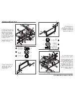
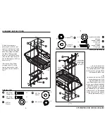
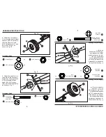
8. Fije las cuatro ruedas
(I) colocando primero los
espaciadores para las
ruedas (II) en cada eje, y
luego las ruedas (I) y las
arandelas planas M12
(JJ), y las contratuercas
M12 (LL), como se
muestra en la Fig. 10.
8
9. Fije la manija (J) a la
horquilla en el ensamble
del eje frontal (H) con el
perno cabeza de botón
interna M8 x 60 mm
(AA), la contratuerca M8
(KK) y la arandela M8
(GG), como se muestra
en la Fig. 11.
Aditamentos utilizados
X 4
Espaciador
para las ruedas
Arandela
plana M12
X 4
Contratuerca
M12
X 4
II
JJ
LL
Fig. 10
I
II
JJ
LL
Fig. 11
Aditamentos utilizados
X 1
M8 x 60mm
Perno cabeza
de botón interna
x 1
x 1
Arandela
plana M8
Contratuerca
M8
AA
KK
GG
ASSEMBLY INSTRUCTIONS
8
Fig. 10
Hardware Used
8. Attach the four wheels
(I) by first placing the wheel
spacers (II) onto each axle,
then the wheels (I) and
M12 flat washers (JJ), and
M12 lock nuts (LL), as
shown in Fig. 10.
I
X 4
Wheel Spacer
II
II
JJ
JJ
M12 Flat Washer
X 4
LL
LL
M12 Lock Nut
X 4
Fig. 11
Hardware Used
9. Attach the handle (J) to
the yoke on the front axle
assembly (H) using the M8
x 62mm internal button
head (AA), M8 lock nut
(KK), and M8 washer (GG),
as shown in Fig. 11.
AA
X 1
M8 x 62mm
Internal Button
Head Bolt
x 1
x 1
M8 Flat Washer
KK
M8 Lock Nut
GG
AA
GG
KK
H
J
AA
GG
KK
H
J
Summary of Contents for GOR2541D
Page 2: ......


