INSTRUCCIONES DE ENSAMBLAJE
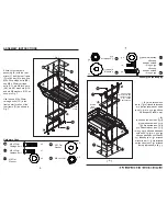
Fig. 8
Aditamentos utilizados
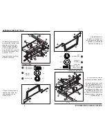
6. Fije la estructura posterior
(D) a la estructura delantera (F)
pernos cabeza de botón interna
M8 x 20 mm (EE), dos
contratuercas M8 (KK) y cuatro
arandelas M8 (GG), como se
muestra en la Fig. 8.
7
x 2
x 2
Arandela plana
M8
Contratuerca
M8
x 2
Aditamentos utilizados
x 3
x 3
Arandela plana
M8
Contratuerca
M8
x 3
Fig. 9
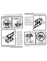
7. Fije el ensamble del seguro del
porta-basura (B) a la bandeja (A)
con tres pernos cabeza de hongo
M8 x 20 mm (CC), tres
contratuercas M8 (KK), tres
arandelas M11 (HH), y tres
arandelas M8 (GG), como se
muestra en la Fig. 9.
Si el ensamble del seguro del
porta-basura (B) no se engancha
cuando baja la bandeja del carrito
(A), revise dos veces la ubicación
de la estructura posterior (D) en el
paso 4.
M8 x 20mm
pernos cabeza
de hongo
M8 x 20mm
Perno cabeza
de botón interna
KK
GG
EE
KK
GG
CC
x 3
HH
Arandela
plana M11
A
B
GG
CC
HH
KK
ASSEMBLY INSTRUCTIONS
Fig. 8
Hardware Used
6. Attach the rear frame (D) to
the front frame (F) using two M8
x 20mm internal button head
bolts (EE), two M8 lock nuts
(KK), and two M8 washers (GG),
as shown in Fig. 8.
7
x 2
x 2
M8 Flat Washer
KK
M8 Lock Nut
GG
D
F
EE
EE
GG
KK
x 2
Hardware Used
x 3
x 3
x 3
Fig. 9
7. Attach the dump lock assembly
(B) to the tray (A) using three M8
x 35mm carriage bolts (CC),
three M8 lock nuts (KK), three
M11 washers (HH), and three M8
washers (GG), as shown in Fig.
9. If the dump lock assembly (B)
does not engage when you lower
the cart tray (A), please double
check the placement of the rear
frame (D) in Step 4.
M8 x 20mm
Internal Button
Head Bolt
EE
M8 Flat Washer
KK
M8 Lock Nut
GG
M8 x 35mm
Carriage Bolt
CC
A
B
GG
CC
HH
KK
x 3
HH
M11 Flat
Washer
D
F
EE
EE
GG
KK
Summary of Contents for GOR2541D
Page 2: ......


