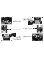
Step 3
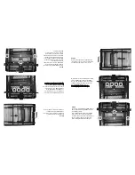
A) Unlock the front frame using the dump
lock and place the rear axle assembly under
the frame to prop it up for easier access.
B) Attach the front axle assembly to the bed
frame using M8x20 carriage bolts (4), M8
washers (4), and M8 lock nuts (4). The bolts
should go through the frame first then the
front axle. Hand tighten.
DDoo nnoott ffuullllyy ttiigghhtteenn bboollttss aatt tthhiiss ttiim
mee..
Step 4
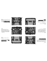
Secure the steering linkage using M6x17 hex
bolts (2), M6 washers (2), and M6 lock nuts
(2). Tighten securely.
Place the M8x15 hex head bolt (1) and M8
lock nut (1) in the center of the front axle
assembly. This bolt is not for connecting any
parts. It is only used for a steering stop
when rotating the wheels left and right.
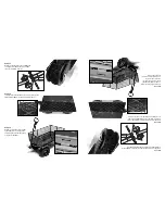
Paso 3
Desbloquear el armazón delantero
mediante el cerrojo de volcar y colocar el
ensamblado del eje trasero bajo el
armazón para alzarlo y facilitar el acceso.
Fijar el ensamblado del eje delantero al
armazón de la cama con (4) pernos de
carro M8x20, (4) arandelas M8 y (4)
contratuercas M8. Los pernos primero
deben pasar por el armazón y luego por el
eje delantero. Apretar con las manos.
N Noo
a apprr
e ettaa
r r cc
o omm
p pllee
t taamm
e enntt
e e lloo
s s pp
e errnn
o oss..
Paso 4
Fijar el acoplamiento de la dirección con
los pernos hexagonales M6x17 (2), las
arandelas M6 (2) y las contratuercas M6
(2). Apretar firmemente.
Colocar el perno de cabeza hexagonal
M8x15 (1) y la contratuerca M8 (1) en el
centro del ensamblado del eje frontal.
Este perno no es para conectar ninguna
pieza. Solamente se usa para frenar
cuando se roten las ruedas hacia la
izquierda y derecha.
Summary of Contents for GORMP-12
Page 2: ......

