GMS SERIES
OM-04386
PAGE E-13
MAINTENANCE AND REPAIR
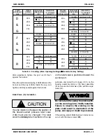
105 MIN.
1.23 FULLY OUT
125
.90
150
.70
175
.55
190 MAX.
.37 FULLY IN
55 MIN.
1.23 FULLY OUT
75
.89
100
.51
110 MAX.
.37 FULLY IN
50 MIN.
1.17 FULLY OUT
100
.93
125
.83
150
.72
175
.61
200
.50
240 MAX.
.31 FULLY IN
30 MIN.
1.17 FULLY OUT
50
.88
75
.57
95 MAX.
.31 FULLY IN
100 MIN.
.60 FULLY OUT
125
.51
150
.42
175
.33
200
.23
225 MAX.
.16 FULLY IN
50 MIN.
.60 FULLY OUT
75
.47
100
.33
130 MAX.
.16 FULLY IN
CRACKING
PRESSURE
(PSI)
D
&
G
PUMP
HYDRAULIC
SIZE
SINGLE
SPRING
OPTION CODE
DOUBLE
SPRING
OPTION CODE
DIMENSION
“A” (INCHES)
(Fig. E‐7)
CRACKING
PRESSURE
(PSI)
J
&
N
R
DIMENSION
“A” (INCHES)
(Fig. E‐7)
STD
25D
25G
25J
STD
25D
25G
25J
STD
25D
25G
25J
25A
25E
25H
25K
25A
25E
25H
25K
25A
25H
25K
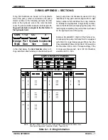
Table E‐3 . Cracking (Valve Opening) Settings ( Denotes Factory Setting)
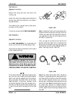
After adjustment, tighten the jam nut (D) flush
against the bonnet.
Place the optional warning tag (10AR) between the
bonnet and the cap (10AN). Install the cap, and
tighten until fully seated against the bonnet.
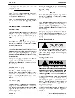
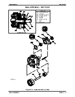
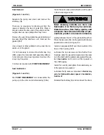
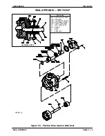
Relief Valve (10) Installation
If pump rotation is changed, the position of
the head‐mounted pressure relief valve
(10A) must also be changed. The relief
valve must
always
be mounted so the cap
on the relief valve is positioned toward the
suction port.
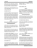
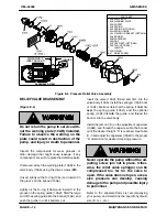
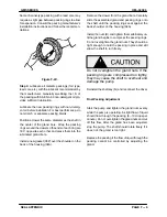
Lubricate and install the O‐ring(s) (10C) on the
housing assembly (04A) or the head assembly
(01A). Secure the relief valve (10A) with the caps
crews (B).
Do not return the pump to service with
out the warning plate (10AB) installed.
Failure to observe the warning on the
plate could result in destruction of the
pump, and injury or death to personnel.
If the warning plate (10AB) has been removed, se
cure it with the drive screws (BM).

