OM-04386
GMS SERIES
PAGE F - 4
SEAL APPENDIX
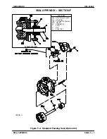
Seal Removal
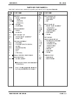
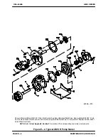
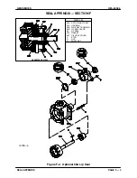
(Figures E‐1 and F‐2)
Separate the pump and driver and remove the
shaft key (N).
There are no provisions for draining oil from the
reservoir between the two oil seals (05). Place a
drip pan under the drive end of the pump and thor
oughly clean up any spillage that may occur.
Remove the nuts (D) and slide the gland (04N) and
lip seals (05)off the shaft as a unit. Remove the
gasket (05P).
Use a dowel or other suitable tool to press the lip
seals out of the gland.
It is not necessary to remove the shaft snap ring
(05D) unless the rotor and shaft assembly (03A) is
to be removed. Use snap ring pliers to remove the
snap ring if required.
Continue as required with
PUMP DISASSEMBLY
.
Seal Installation
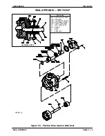
(Figures E‐1 and F‐2)
See
PUMP REASSEMBLY
, and reassemble the
pump up to the rotor and shaft assembly (03A).
Clean the seal cavity and shaft with a cloth soaked
in fresh cleaning solvent.
Most cleaning solvents are toxic and
flammable. Use them only in a well ven
tilated area free from flame, sparks, and
excessive heat. Read and follow all pre
cautions printed on solvent containers.
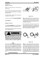
Lightly lubricate the I.D. of the gland (04N) with oil.
Press the lip seals (05) into the gland with the lips
positioned as shown in Figure F‐2.
Install a new gasket (05P) over the shoulder on the
back of the housing (04A).
Lubricate the lip seal areas on the shaft with oil.
Carefully slide the assembled gland and lip seals
onto the shaft until the gland seats against the gas
ket.
Use caution
not to roll or cut the lip seals on
the shaft keyway.
Install the nuts (D) and tighten them alternately un
til the gland is fully seated.
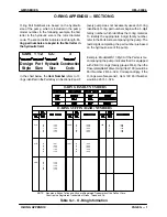
Lubricate the lip seals as indicated in
Barrier Liq
uids for Optional Double Lipseal
in
Installation,
Section B
.
Reinstall the shaft key (N) and reconnect the driver.

