OM-04386
GMS SERIES
PAGE F - 6
SEAL APPENDIX
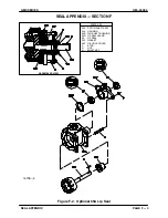
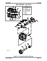
Seal Removal
(Figures E‐1 and F‐3)
Remove the nuts (D) and slide the gland (04N) and
stationary seal components off the shaft as a unit.
Press the seal stationary seat and O‐ring out of the
gland from the back side. Remove the gasket
(05P).
Use an allen wrench to loosen the seal retainer set
screws. Lightly oil the shaft and slide the rotating
portion of the seal off the shaft.
It is not necessary to remove the shaft snap ring
(04R) unless the rotor and shaft assembly (03A) is
to be removed. Use snap ring pliers to remove the
snap ring if required.
Continue as required with
PUMP DISASSEMBLY
.
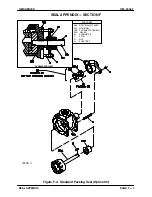
Seal Installation
(Figures E‐1 and F‐3)
See
PUMP REASSEMBLY
, and reassemble the
pump up to the backhead kit (06).
Clean the seal cavity and shaft with a cloth soaked
in fresh cleaning solvent.
Most cleaning solvents are toxic and
flammable. Use them only in a well ven
tilated area free from flame, sparks, and
excessive heat. Read and follow all pre
cautions printed on solvent containers.
The seal is not normally reused because wear pat
terns on the finished faces cannot be realigned
during reassembly. This could result in premature
failure. If necessary to reuse an old seal in an emer
gency,
carefully
wash all metallic parts in fresh
cleaning solvent and allow to dry thoroughly.
Seal components
must
be kept clean.
Handle seal parts with extreme caution to
prevent damage. Use care not to contami
nate the precision‐finished faces; even fin
gerprints on the faces can shorten seal life.
If necessary to clean the faces, use a clean
cloth and wipe in a circular pattern.
Inspect the seal components for wear, scoring,
grooves, and other damage that might cause leak
age. If any components are worn, replace the com
plete seal;
never mix old and new seal parts
.
If a replacement seal is being used, unwrap the
mechanical seal components. Check that the seal
faces are clean, undamaged and free if any foreign
matter.
New seal assemblies may be equipped
with spring holding clips for storage pur
poses. Do not remove these clips until the
seal is installed on the pump shaft. Once
the seal is installed, remove and discard
these clips using caution so that they do
not pop off abruptly and cause personal in
jury. Failure to remove these clips will result
in seal failure and possible pump damage.
If removed, install the shaft snap ring (04R) in the
groove in the rotor/shaft assembly (03A). Lightly oil
the shaft of the rotor/shaft assembly. Position the
rotating portion of the seal on the shaft with the
sealing face toward the drive end of the shaft.
When the seal is positioned on the full diameter of
the shaft, carefully remove the spring holding clips.
Continue to slide the seal onto the shaft until the
spring retainer seats against the snap ring (05D).
Secure the rotating portion of the seal to the shaft
by tightening the setscrews in the drive band.
Lubricate the stationary element O‐ring with light
oil. Position the stationary element in the gland
(04N) with the sealing face up. Cover the sealing
face with a clean tissue. Use a push tube (I.D.
slightly larger than the shaft diameter) to press the
stationary element into the gland until fully seated.
Install a new gasket (05P). Carefully slide the as
sembled gland and stationary seal components
onto the shaft until the sealing faces contact. Install
the nuts (D) and tighten them alternately until the
gland is fully seated.
Reinstall the shaft key (N) and reconnect the driver.


