OM−05229
JSV3H
PAGE E − 10
MAINTENANCE AND REPAIR
3.
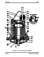
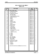
Slide the lower bearing (207) onto the shaft un-
til fully seated, install the support ring (208),
and secure with the retaining ring (209).
NOTE
If the bearings were heated, allow them to cool and
then check to make sure that they has not shrunk
away from the shaft shoulders. If the bearings have
shifted, use a suitable sleeve and a press to fit the
bearings snug against the shoulders.
4.
If heating the bearings is not practical, use an
arbor (or hydraulic) press and a suitable sized
sleeve to press the bearings onto the shaft until
fully seated.
5.
Slide the rotor and shaft and assembled bear-
ings into the lower bearing housing (213) until
the lower bearing (207) is fully seated, and se-
cure the bearing with the retaining ring (206).
Installing Shaft and Rotor Assembly
NOTE
The stator (301) is a hot shrink fit in the motor hous-
ing (302). No instructions are given in this manual
for separating the stator, motor housing, or thermal
protectors (307). It is strongly recommended that
the stator/motor housing be returned to the factory
or an authorized Gorman-Rupp repair facility if any
of the components require service.
1.
Lightly lubricate a new O-ring (252) and install
it in the groove in the bearing housing (213).
2.
Slide the assembled rotor and shaft and lower
bearing housing into the motor housing, and
use a soft-faced mallet to tap around the lower
bearing housing until fully seated in the stator
housing (302).
3.
After the motor is fully assembled, lubricate the
motor as indicated in
LUBRICATION
at the
end of SECTION E.
Installing Motor Cover
1.
Clean the exterior of the motor cable (234) with
warm water and mild detergent, and inspect
for obvious damage. (If required, see
ELEC-
TRICAL TESTING
in
TROUBLESHOOTING
,
SECTION D.)
Do
not
splice the cable. waterproof integri-
ty must be maintained. If repairs are re-
quired other than at either end, replace the
entire cable.
2.
If the cable inlet (236), cable clamp (238), and
rubber seal (235) have been moved or re-
moved, lubricate the motor cable (234) to ease
moving the parts during installation.
3.
Install the cable inlet (236) and cable clamp
(238). Discard the old rubber seal (235) and in-
stall a new one above the deformation mark left
on the motor cable by the old seal.
4.
Cut the motor cable (234) above the seal defor-
mation mark. Strip the motor cable outer insu-
lation so that the individual leads are long
enough to make motor connections; the
ground lead must be longer than the others.
5.
Remove the identification sleeves from the cut
power leads, and install on the new wire ends.
Install identifying sleeves or markers identical
to those on the old leads on the new leads.
6.
Pull the rubber seal (235) down to within two
inches (50,8 mm) of the end of the motor cable
sheath (234). Pull the cable clamp (238) down
until flush with the rubber seal. Lubricate the
outside of the cable clamp, and pull the cable
inlet (236) down over the clamp until flush with
the cable clamp.
7.
Insert the motor cable leads into the motor
cover (230), making certain that the rubber
seal bottoms in the cover, and that the cable
clamp (238) and cable inlet (236) are flush with
the top of the cover. Secure the cable inlet and
installed components with the screws (237).

