JSV3H
OM−05229
PAGE B − 3
INSTALLATION
Field Wiring Connections (Incoming Power)
Field wiring is
not
provided with this pump, and
must be supplied by the user. The field wiring must
be of the proper size and type to ensure an ade-
quate voltage supply to the pump. Voltage avail-
able at the motor must be within the range indi-
cated in Table B-2.
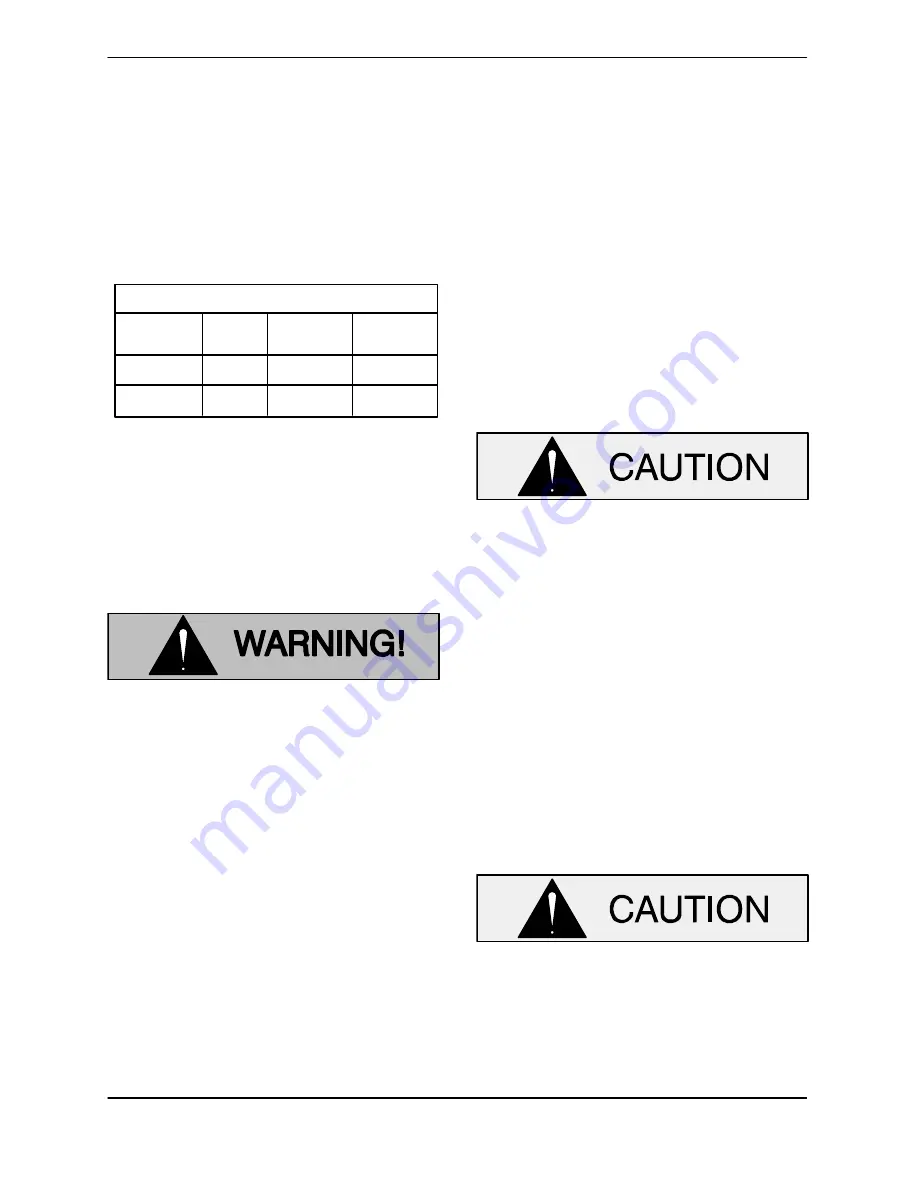
TABLE B-2. MOTOR VOLTAGE LIMITS
NOMINAL
VOLTAGE
3
200
180
220
PHASE
MINIMUM
VOLTAGE
MAXIMUM
VOLTAGE
3
230
205
260
Use conduit cable clamps to secure the incoming
field wiring to the control box. Make certain all con-
nections are tight. If necessary, support the cable
weight to prevent excessive strain on cable clamps
and cable.
Motor Cable Grounding Test
Do not connect the pump control cable
to the control box or incoming voltage
before verifying the pump ground;
otherwise, personnel will be exposed to
serious injury or death.
Connect one lead of lamp, bell or similar testing de-
vice to motor cable green/yellow ground lead.
Connect second test lead to an
uninsulated
point
on the pump body. The test circuit should close.
If the test circuit does not close there is a defect in
the cable or motor which must be corrected.
Conductor Identification
The conductors in the pump cable are labeled
when shipped from the factory. If the conductors
are shortened in the field, resulting in loss of identi-
fication markers, they can still be identified by their
location relative to the ground wire.
Refer to FIGURE B−1; as seen from the free end of
the cable, the conductor immediately adjacent to
and clockwise from ground (green/yellow) is as-
signed number T1. The second clockwise conduc-
tor is T2, etc.
The conductors labeled P1 and P2 are for thermal
and moisture sensor connections, respectively.
If the conductors are relabled, they should be iden-
tified with wire markers from the factory.
Wiring Diagram and Control Box Connections
The pump warranty is void if the motor is
not operated through a control box ap-
proved by Gorman-Rupp.
This pump is shipped completely wired for the volt-
age shown on the nameplate, and is ready for op-
eration through an approved control box.
Ground the control box in accordance with the in-
structions accompanying it.
Refer to FIGURE B−1, and wire the motor to a con-
trol which will provide the connections shown.
Control leads P1 and P2 provide the motor with
moisture and thermal protection. Note that thermal
protection is supplementary
only
; separate Class
10 overload relays are required for motor running
protection.
The thermal protection contacts will auto-
matically reclose when the motor cools to
the established safe operating tempera-
ture. Whenever automatic restarting is not
desirable, connect only to controls which
are wired for manual restart.


