background image

OM−00974

80 SERIES

MAINTENANCE & REPAIR

PAGE E − 5

wise  until it rests against the cover (see Figure 4) to
prevent the grease in the cup from escaping. Re-
move the grease cup and piping (11, 12, 13, 14
and 15).

Immobilize the impeller by wedging a block wood
between the vanes. Remove the impeller caps-
crew, lock washer and washer (46, 47 and 48). If
removed, install the shaft key (23). Install a lathe
dog on the drive end of the shaft (26) with the V"
notch positioned over the shaft keyway.

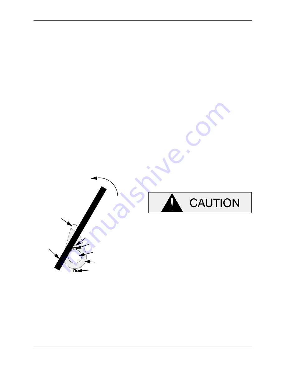
With the impeller rotation still blocked, strike the
lathe dog sharply in a counterclockwise direction
(when facing the drive end of the shaft). The impel-
ler may also be loosened by using a long piece of
heavy bar stock to pry against the arm of the lathe
dog in a counterclockwise direction (when facing
the drive end of the shaft) as shown in Figure 2.

Use caution

 not to damage the shaft or keyway.

When the impeller breaks loose, remove the lathe
dog and wood block and unscrew the impeller
from the shaft.

Turn

Counterclockwise

Lathe Dog Arm

V" Notch

Shaft Key

Impeller Shaft

Lathe Dog

Setscrew

Heavy

Bar Stock

Figure 2.  Loosening Impeller

Unscrew the impeller from the shaft. Use caution
when removing the impeller; tension on the seal
spring will be released as the impeller is un-
screwed.

Inspect the impeller and replace it if cracked or
badly worn. Slide the impeller adjusting shims (64)
and seal washer (63) off the impeller shaft. Tie and

tag the shims, or measure and record their thick-
ness for ease of reassembly.

Seal Removal and Disassembly

Remove the outer rotating element. Slide the seal
plate, shaft sleeve, and remaining seal parts off the
shaft as a unit. Carefully remove the stationary and
rotating seal elements, packing rings and wash-
ers, seal spring and spacer sleeve from the seal
plate.

Inspect the seal plate and replace it if cracked or
badly worn. Inspect the seal liner (65) for wear or
grooves that could cause leakage or damage to
the seal packing rings. The seal liner is a press fit
into the seal plate and does not normally require re-
placement. If replacement is required, see 

Seal

Installation

.

Shaft And Bearing Removal And Disassembly

When the pump is properly operated and main-
tained, the pedestal should not require disassem-
bly. Disassemble the shaft and bearings 

only

when there is evidence of wear or damage.

Shaft and bearing disassembly in the field
is not recommended. these operations
should be performed only in a properly-
equipped shop by qualified personnel.

Remove the pedestal drain plug (32) and drain the
pedestal. Clean and reinstall the plug.

Remove the slinger ring (16) from the shaft. Re-
move the pedestal mounting hardware from the
base. Tie and tag any shims used under the
mounting feet for leveling.

Use snap ring pliers to remove the bearing retain-
ing ring (28) from the pedestal bore. Remove the
bearing shim set (29); tie and tag the shims, or
measure and record their thickness for ease of
reassembly.

Loosen. but do not remove, the two machine
screws (24) in the bearing retainer (21) and pry the
retainer from the pedestal bore using a pair of

Summary of Contents for 88A2-B

Page 1: ...MAN RUPP COMPANY D MANSFIELD OHIO www grpumps com GORMAN RUPP OF CANADA LIMITED D ST THOMAS ONTARIO CANADA Printed in U S A eCopyright by the Gorman Rupp Company INSTALLATION OPERATION AND MAINTENANCE...

Page 2: ...rial number and e mail address required RECORD YOUR PUMP MODEL AND SERIAL NUMBER Please record your pump model and serial number in the spaces provided below Your Gorman Rupp distributor needs this in...

Page 3: ...ps PAGE B 3 Suction Line Positioning PAGE B 3 DISCHARGE LINES PAGE B 4 Siphoning PAGE B 4 Valves PAGE B 4 Bypass Lines PAGE B 4 ALIGNMENT PAGE B 5 Coupled Drives PAGE B 5 V Belt Drives PAGE B 5 V BELT...

Page 4: ...moval PAGE E 4 Impeller Removal PAGE E 4 Seal Removal and Disassembly PAGE E 5 Shaft And Bearing Removal And Disassembly PAGE E 5 Shaft And Bearing Reassembly And Installation PAGE E 6 Seal Reassembly...

Page 5: ...on Pumps and related equipment must be installed and operated ac cording to all national local and industry stan dards If there are any questions regarding the pump or its application which are not co...

Page 6: ...es 6 Vent the pump slowly and cau tiously 7 Drain the pump This pump is designed to handle most non volatile non flammable liquids containing specified entrained solids Do not attempt to pump liquids...

Page 7: ...sly 6 Refer to instructions in this manual before restarting the pump Do not remove plates covers gauges pipe plugs or fittings from an over heated pump Vapor pressure within the pump can cause parts...

Page 8: ...ped with a Gorman Rupp double grease lubricated seal therefore the maximum incoming pressure must be limited to 10 p s i For further assistance contact your Gorman Rupp distributor or the Gorman Rupp...

Page 9: ...emove all customer installed equipment such as suction and discharge hoses or piping before attempting to lift existing installed units The pump assembly can be seriously damaged if the cables or chai...

Page 10: ...y the pump user make certain that the total area of the openings in the strainer is at least three or four times the cross section of the suction line and that the openings will not permit passage of...

Page 11: ...ge line use a valve as large as the largest pipe to minimize friction losses Never install a throttling valve in a suction line With high discharge heads it is recommended that a throttling valve and...

Page 12: ...in both the horizontal and vertical planes Most couplings require a specific gap or clearance between the driving and the driven shafts Refer to the coupling manufacturer s service literature Align s...

Page 13: ...ion v belts Over tensioning will short en both v belt and bearing life Under tensioning will cause belt slippage Always keep belts free from dirt grease oil and other foreign material which may cause...

Page 14: ...large O ring is even with the top of the next belt or with the bottom of a straight edge laid across the sheaves Read the force applied from the bottom of the small O ring on the deflection force sca...

Page 15: ...500 1740 1741 3000 15 5 14 6 23 4 21 8 17 1 16 8 25 5 25 0 8V 12 5 17 0 200 850 851 1500 33 0 26 8 49 3 39 9 200 850 851 1500 39 6 35 3 59 2 52 7 18 0 22 4 Table 2 Sheave Diameter Millimeters Deflect...

Page 16: ...xtended operation of a dry pump will destroy the seal assembly Add liquid to the pump casing when 1 The pump is being put into service for the first time 2 The pump has not been used for a consider ab...

Page 17: ...tion line for leaks After the pump has been primed partially close the discharge line throttling valve in order to fill the line slowly and guard against excessive shock pres sure which could damage p...

Page 18: ...freezing conditions drain the pump to prevent damage from freezing Also clean out any solids by flushing with a hose Operate the pump for approximately one minute this will remove any remaining liqui...

Page 19: ...e Air leak in suction line Lining of suction hose collapsed Correct leak Replace suction hose Leaking or worn seal or pump gasket Check pump vacuum Replace leaking or worn seal or gasket Suction lift...

Page 20: ...ng s frozen Disassemble pump and check bearing s Liquid solution too thick Dilute if possible Discharge flow too slow Open discharge valve fully to in crease flow rate and run power source at maximum...

Page 21: ...ly the same duty cycle the part can be checked and replaced before failure occurs reducing unscheduled down time For new applications a first inspection of wearing parts at 250 hours will give insight...

Page 22: ...with minimum suction lift Since pump installations are seldom identical your performance may be dif ference due to such factors as viscosity specific gravity elevation temperature and impeller trim If...

Page 23: ...80 SERIES OM 00974 MAINTENANCE REPAIR PAGE E 2 SECTION DRAWING PARTSPAGE Figure 1 Pump Model 88A2 B...

Page 24: ...SHIM SET 8546 15990 1 30 SIGHT GAUGE S1471 1 31 PIPE PLUG P12 15079 1 32 PIPE PLUG P06 15079 1 33 O RING 25152 248 1 34 BEARING CAP 38322 418 10010 1 35 OIL SEAL 25227 534 1 36 STUD C0607 15991 6 37 H...

Page 25: ...miliarize yourself with this man ual 2 Lock out or disconnect the power source to ensure that the pump will remain inoperative 3 Allow the pump to completely cool if overheated 4 Check the temperature...

Page 26: ...s or measure and record their thick ness for ease of reassembly Seal Removal and Disassembly Remove the outer rotating element Slide the seal plate shaft sleeve and remaining seal parts off the shaft...

Page 27: ...loth Re place the shaft if defective Clean the bearings thoroughly in fresh cleaning solvent Dry the bearings with filtered compressed air and coat with light oil Bearings must be kept free of all dir...

Page 28: ...eated Install a new O ring 33 in the groove in the bear ing cap Slide the assembled bearing cap and oil seal over the shaft until fully seated against the pedestal Use caution not to roll or cut the l...

Page 29: ...water or a very small amount of oil and apply a drop of light lubricating oil on the fin ished faces Assemble the seal as follows see Fig ure 3 IMPELLER SHAFT STATIONARY SEAT STATIONARY WASHERS ROTAT...

Page 30: ...64 as previously removed and screw the impeller onto the shaft until tight Make sure the seal spring seats squarely over the step on the back of the impeller The clearance between the back of the imp...

Page 31: ...s The pedestal was fully lubricated when shipped from the factory Check the oil level regularly through the sight gauge 30 and maintain it at the middle of the gauge When lubrication is required add S...

Page 32: ...rpumps com warranty or call U S 419 755 1280 International 1 419 755 1352 For Canadian Warranty Information Please Visit www grcanada com warranty or call 519 631 2870 THE GORMAN RUPP COMPANY D MANSFI...

Reviews: