background image


INSTALLATION 

AND START-UP


Summary of Contents for VG3B3-B

Page 1: ...E MANUAL AUGUSTA CORRECTIONAL FACILITY CRAIGSVILLE VIRGINIA PROJECT I D 107150D 2008 Aqua Aerobic Systems Inc All rights reserved This manual may not be copied all or in part without the express writt...

Page 2: ...chie Environmental Solutions LLC 1100 Welborne Drive Suite 100 6209 Lansgate Road Richmond VA 23229 Midlothian VA 23112 Phone 804 740 0181 Phone 804 928 8499 AQUA AEROBIC PROJECT MANAGER Dan Durdan 63...

Page 3: ...s EP 10005 D Outline for Manufacturers Training EP 10030 E Warranty Documents F U L Motor Requirements 1 Teco G Receiving and Handling EP 10031 1 Freight Loss Form EP 10032 H Protective Coatings 1 Tec...

Page 4: ...Lubricant EP 50012 K List of Spare Parts L Guarantee Documents SECTION 2 INSTALLATION and START UP A Double Nut Procedure EP 10080 1 Bolt Torque Specification ES 1057 B Start up Papers 1 Aqua UltraFil...

Page 5: ...co 7 5 HP 1800 RPM 2616716 2 2 Backwash a Gorman Rupp VG3C3 B 2616695 b Teco 20HP 1800 RPM 2616696 2 E Valve Schedule 1 Butterfly a Manual Lever i 3 inch Wafer Style Butterfly 2612364 ii 4 inch Wafer...

Page 6: ...ft 2702606 4 USB Cable 2751221 5 PVC Flex EP 10260 D Circuit Breaker 1 1 Amp 2751347 2 2 Amp 2751349 3 3 Amp 2751350 4 5 Amp 2751352 5 6 Amp 2751353 6 10 Amp 2751356 7 10 Amp 2752206 8 15 Amp 2751358...

Page 7: ...30 Amp 3 Pole Pri Trans Allen Bradley 2702123 4 Class CC 30 Amp 2 Pole Pri Trans Allen Bradley 2702122 5 Class CC 30 Amp 1 Pole Sec Trans Allen Bradley 2702121 6 Electronic 15 Amp 1 Pole Analog 275003...

Page 8: ...835 2 CompactLogix Analog Output Module 2702282 3 CompactLogix Digital IO Input Module 2701824 4 CompactLogix Digital IO Output Module 2701834 5 CompactLogix Processor 2751387 6 CompactLogix End Cap R...

Page 9: ...1 12 Power Block Cover 2752652 13 Power Splicer Block 2752531 14 Power Block Cover 2752387 15 Power Splicer Block 2752535 16 Power Block Cover 2752536 W Timer 1 Time Delay Relay 2702283 2 Relay Socket...

Page 10: ...iv Krohne 2000 F Supplement EP 50045 b Turbidity Monitoring O M i Hach 1720E EP 50040 ii Hach 660 sc EP 50305 c Controller i Thermo Scientific AV38 EP 50285 d pH Probe i Thermo Scientific pH EP 50290...

Page 11: ...tl Permeate Holding Tank Q 9107150D7075 Mixer Installation Membrane Feed Tank R 2965017 Kit Adhesive Anchor 0 50 in SET S 2965556 Nameplate Installation Concrete Wall T 2966227 Assembly Valve 8 inch E...

Page 12: ...LL 9107150D7711 Sh 1 Membrane Power Panel Assembly MM 9107150D7711 Sh 2 Membrane Power Panel Assembly NN 9107150D7711 Sh 3 Membrane Power Panel Assembly OO 9107150D7711 Sh 4 Membrane Power Panel Assem...

Page 13: ...LLL 9107150D7722 Sh 4 Membrane Backwash Pump Remote I O Panel Elementary MMM 9107150D7723 Sh 1 Membrane Remote I O Panel Elementary NNN 9107150D7723 Sh 2 Membrane Remote I O Panel Elementary OOO 91071...

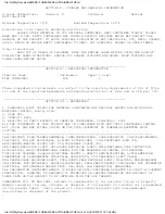
Page 14: ...GENERAL INFORMATION...

Page 15: ...Market Services Or e mail Customer Service at customerservice aqua aerobic com Ordering replacement parts and or equipment may be done via our Fax number Please send order via Fax 815 654 8623 to the...

Page 16: ...t in death or serious injury Danger is limited to the most extreme situations WARNING Indicate a potentially hazardous situation which if not avoided could result in death or serious injury CAUTION In...

Page 17: ...EQUIPMENT SAFETY DOCUMENTS and PRECAUTIONS...

Page 18: ...g o Arc blast impacts The heating of air and vaporization of metal during an arc creates a pressure wave that can damage hearing and cause concussions among other injuries o Falls Electric shocks and...

Page 19: ...of identifying the individual who tagged it and the reason why it was tagged Individual lockout devices with worker s name and picture on them are preferred That worker must be the only person who ha...

Page 20: ...ting clothing Arc blast impacts The heating of air and vaporization of metal creates a pressure wave that can damage hearing and cause memory loss from concussion and other injuries Flying metal parts...

Page 21: ...r circuit part with an adequately rated voltage detector to verify that the equipment is de energized Test each phase conductor or circuit part both phase to phase and phase to ground Check the voltag...

Page 22: ...oach distance to exposed live parts to prevent flashover or arcing Approaching any closer is comparable to making direct contact with a live part Arc Flash Hazard The Flash Protection Boundary is the...

Page 23: ...ords in wet or damp locations and Keep electrical cords away from standing water Other Precautions When working on de energized parts but still inside the flash protection boundary for nearby live exp...

Page 24: ...if labels become unreadable Do not work on equipment alone Always wear eye protection when using power tools or when working around rotating equipment Exercise all necessary precautions with regard t...

Page 25: ...e should be performed by qualified personnel Treat all electrical equipment and conductors as though they are energized until they are placed in an electrically safe work condition Create an electrica...

Page 26: ...n proper use of the equipment let them do it 4 Preventative Maintenance 4 1 Reference preventative maintenance list including 4 1 1 Reference material 4 1 2 Daily weekly monthly quarterly semi annual...

Page 27: ...the date the goods are put into service or eighteen 18 months from shipment of equipment whichever first shall occur The Endura Series AquaDDM Mixers will be warranted for a period of 3 three years fo...

Page 28: ...rom shipment of equipment whichever first shall occur 5 PROCESS PERFORMANCE WARRANTY In accordance with Specification Sections 11400 3 2A 3 3 11410 3 2A 3 3 and 11420 3 2A 3 3 Aqua Aerobic guarantees...

Page 29: ...r applied operated or installed contrary to our instruction or subjected to misuse chemical attack degradation negligence or accident This warranty and any warranty and guaranty of process or performa...

Page 30: ...U L MOTOR REQUIREMENTS...

Page 31: ......

Page 32: ...pertinent to each of these components If there are shortages on any shipment the packing slip will indicate that the item is back ordered or shipping direct from original supplier All items back order...

Page 33: ...igging should be used Short cables or chains can put a cross shear on the lift eyes breaking them off or otherwise damaging the motor or causing a threat of falling The lift must be equal and level A...

Page 34: ...ice of articles amount of claim etc _________________________________________________________________________________________________________________ Total Amount Claimed IN ADDITION TO THE INFORMATIO...

Page 35: ...PROTECTIVE COATINGS...

Page 36: ...ors Parts A Preparation Painting TECO MOTOR PAINT SPECIFICATION SURFACE TREATMENT SHOT BLASTING SSPC SP10 Procedures Paints Color Film Thickness Manufacturer Primary Coating Epoxy Ester Light Green 25...

Page 37: ...PAINT TECHNICAL DATA SHEETS...

Page 38: ...Coating Specification Base and Topcoat Tnemec Series N69 Hi Build Epoxoline II Polyamidoamine Epoxy paint Top coating Tnemec Series 1075 Endura Shield II Aliphatic Acrylic Polyurethane paint Applicati...

Page 39: ...TION PRIMED STEEL Immersion Service Scarify the Series 66 N69 V69 or 161 prime coat surface by abrasive blasting with fine abrasive before topcoating if it has been exterior exposed for 60 days or lon...

Page 40: ...r at 100 F 38 C APPLICATION EQUIPMENT Air Spray Gun Fluid Tip Air Cap Air Hose ID Mat l Hose ID Atomizing Pressure Pot Pressure DeVilbiss JGA E 765 or 704 5 16 or 3 8 7 9 or 9 5 mm 3 8 or 1 2 9 5 or 1...

Page 41: ...nced for the most current technical data and instructions or you may contact your Tnemec representative for current technical data and instructions TECHNICAL DATA VOLUME SOLIDS 71 2 0 mixed RECOMMENDE...

Page 42: ...Do not use medium or long nap roller covers Two coats are required to obtain dry film thickness above 3 0 mils 75 microns Brush Recommended for small areas only Use high quality natural or synthetic...

Page 43: ...PASSIVATION DOCUMENTS...

Page 44: ...e film and removes surface iron from the component by application of an acid solution Aqua Aerobic Systems Inc AASI provides two approved stainless steel passivation standards Unless specified otherwi...

Page 45: ...ng final fabrications with weld areas is detailed below Alternate methods of treatment for large fabrications include swabbing and spraying Procedure Weld Areas All stainless steel welded fabrications...

Page 46: ...ess than 16 chromium the test method shall be the salt spray test according to ASTM B117 09 for two hours Testing shall be completed at least 6 hours at room temperature after passivation and reported...

Page 47: ...STORAGE PROCEDURES...

Page 48: ...anifold openings must be sealed off to prevent water and or rodents from entering equipment or piping system that may cause damage All finished surfaces of exposed flanges valves etc must be sealed of...

Page 49: ...age Control panels are top heavy Once upright control panels must be secured to prevent tipping restated from warning label on inner door panel Long Term Storage If the control panel is to be stored u...

Page 50: ...12 04 09 When determining the proper corrosion inhibitor for your application assume the enclosure volume to be protected is greater than calculated if 1 the enclosure doors are opened frequently 2 th...

Page 51: ...INSTRUMENTATION...

Page 52: ...ment away from the elements with temperatures that range from 4 to 40 C 40 to 104 F All electrical cables must be protected from damage and individually tie wrapped in a coil and kept from being kinke...

Page 53: ...oc 1 of 1 Copyright 2008 Aqua Aerobic Systems Inc 2008 10 15 Store the device in a dry dust free location The storage temperature should be between 40 to 149 F 40 to 65 C Avoid continuous direct sunli...

Page 54: ...ter and could create an offset in the transducer output or cause permanent damage For these reasons the level transducers are provided with a sensitive bellows type filter The sensitive bellows filter...

Page 55: ...n Cube When not in use properly store the calibration cube assembly inside its protective box in a cool dry place where ambient temperatures are above freezing Protect from dirt and dust If dirt or du...

Page 56: ...VALVES...

Page 57: ...d building Normal temperature and humidity variations outdoors or in unheated buildings may result in condensation which could accumulate inside un powered actuators If a climate controlled building i...

Page 58: ...PUMPS...

Page 59: ...ribed within the operation and maintenance section will help to prevent rusting of the internal parts or bearings Improper storage of electric motors will also result in seriously reduced reliability...

Page 60: ...re during the entire storage period The pump and or motor shafts and all other exposed surfaces should be painted or coated with Nox Rust X 110 or equivalent Refer to the specific pump and or motor O...

Page 61: ...MATERIAL SAFETY DATA SHEETS...

Page 62: ...azard s identification Composition information on ingredients First aid measures Fire fighting measures Accidental release measures Handling and storage Exposure controls personal protection Physical...

Page 63: ...02 0 1 00 1 00 Niobium 7440 03 1 5 00 5 00 Phosphor 7723 14 0 Yellow 10 10 Silicon 7440 21 3 Respirable dust 5 00 Sulfur 7446 09 5 As sulfur dioxide 5 00 Tin 7440 31 5 2 00 2 00 Titanium 13463 67 7 A...

Page 64: ...r until recovered SKIN Wash with water and a mild detergent EYES Flush thoroughly with water INGESTION While ingestion of large enough quantities to cause health effects is unlikely consult a physicia...

Page 65: ......

Page 66: ...PAINT COATING MSDS...

Page 67: ...IED CYCLOALIPHATIC POLYAMINE 0 10 BENZYL ALCOHOL 100 51 6 4 94103 N BUTANOL SKIN 71 36 3 4 027564 ETHYL BENZENE 100 41 4 2 486291 ISOPHORONE DIAMINE 2855 13 2 2 305814 AMORPHOUS SILICA 7631 86 9 2 258...

Page 68: ...se a cutting torch on the empty drum When used in a mixture read the labels and safety data sheets of all components Wash thoroughly after handling Storage Keep away from heat sparks and flame VAPORS...

Page 69: ...Act Section 112 Hazardous Air Pollutants HAPs see 40 CFR 61 This product contains the following HAPs Component XYLENE ETHYL BENZENE Disclaimer For specific information regarding occupational safety a...

Page 70: ...1330 20 7 6 312195 METHYL ISOBUTYL KETONE 108 10 1 3 922 AROMATIC HYDROCARBON MIXTURE 64742 95 6 3 233301 1 2 4 TRIMETHYLBENZENE 95 63 6 2 399976 1 3 5 TRIMETHYLBENZENE 108 67 8 0 599994 ETHYL BENZEN...

Page 71: ...heets of all components Wash thoroughly after handling Storage Keep away from heat sparks and flame VAPORS MAY CAUSE FLASH FIRE Use only in an area containing flame proof equipment Do not smoke Exting...

Page 72: ...NZENE 95 63 6 2 399976 1 0 ETHYL BENZENE 100 41 4 0 363892 0 1 Clean Air Act Section 112 Hazardous Air Pollutants HAPs see 40 CFR 61 This product contains the following HAPs Component XYLENE METHYL IS...

Page 73: ...ADHESIVE ANCHORS MSDS...

Page 74: ...SIMPSON...

Page 75: ...skin sensitization evidenced by rashes and hives Inhalation Moderate irritation to the nose and respiratory tract May cause Central Nervous System depression evidenced by headache dizziness and nause...

Page 76: ...ners Seal tightly for proper disposal Additional Information Notify authorities if any exposures to the general public or environment occur or are likely to occur Dispose in accordance with federal st...

Page 77: ...or Transport XIV REGULATORY INFORMATION Country Regulatory List USA TSCA EPA SARA Title III Section 312 40 CFR 370 Hazardous Classification Acute Chronic Health Hazard EPA SARA Title III Section 313 4...

Page 78: ...ract May cause Central Nervous System depression evidenced by giddiness headache dizziness and nausea Ingestion May cause irritation to the gastrointestinal tract May cause headache nausea May cause C...

Page 79: ...able non reactive material Place in leak proof containers Seal tightly for proper disposal Additional Information Notify authorities if any exposures to the general public or environment occur or are...

Page 80: ...Section 312 40 CFR 370 Hazardous Classification Acute Chronic Health Hazard EPA SARA Title III Section 313 40 CFR 372 Component s above de minimus level Phenol 4 4 1 methylethylidene bis US California...

Page 81: ...t and Company Identification Product Name SLIC TITE PASTE with PTFE Revision 1 8 Date Prepared December 7 1994 Date Revised February 20 2007 Manufacturer LA CO INDUSTRIES Inc Markal Co 1201 Pratt Blvd...

Page 82: ...personnel removed and upwind of any fire Wear full fire fighting turn out gear full Bunker gear and respiratory protection SCBA Keep containers cool by spraying with water NFPA Rating Health 2 Flammab...

Page 83: ...ents Hazardous Decomposition Products Not Determined Section 11 Toxicological Information Sensitization to Product Not Applicable Irritancy of Product Not Applicable Reproductive Toxicity Not Applicab...

Page 84: ...tion NSF Certified to ANSI NSF Standard 61 United States Department of Agriculture USDA Authorized by USDA for use in federally inspected meat and poultry plants Underwriters Laboratories U L Classifi...

Page 85: ...ilable to us and is accurate and reliable to the best of our knowledge and belief However LA CO Industries Inc makes no representations as to its completeness or accuracy Information is supplied on co...

Page 86: ...ical Name Ingredients SEVERELY REFINED MINERAL OIL Hazard OIL MIST TLV 5 MG M3 1 PEL 5 MG M3 2 STEL 10MG M3 1 CAS 8042 47 5 Chemical Name Ingredients CALCIUM CARBONATE Hazard IRRITANT TLV 3 MG M3 1 PE...

Page 87: ...cute Short Term Exposure INGESTION MAY CAUSE IRRITATION WITH POSSIBLE NAUSEA VOMITING AND DIARRHEA INHALATION MAY CAUSE RESPIRATORY IRRITATION SEEN AS COUGHING AND SNEEZING SKIN CONTACT MAY CAUSE IRRI...

Page 88: ...ATION TEST NON SENSITIZING 3 SKN RBT SUB CHRONIC 28 DAY NON IRRITATING 3 SKN MSE CHRONIC 104 WEEK NO SKIN TUMORS AT SITE OF APPLICATION 3 MODIFIED AMES ASSAY SALMONELLA TYPHIMURIUM NEGATIVE 3 IN VITRO...

Page 89: ...IVE CLOTHING USE CARE AS SPILLS MAY BE SLIPPERY DIKE AND CONTAIN SPILL ABSORB WITH AN INERT MATERIAL AND TRANSFER ALL MATERIAL INTO A PROPERLY LABELED CONTAINER FOR DISPOSAL PREVENT PRODUCT FROM CONTA...

Page 90: ...TS OF THIS PRODUCT ARE IN COMPLIANCE WITH THE TOXIC SUBSTANCES CONTROL ACT TSCA AND ARE EITHER LISTED ON THE TSCA INVENTORY OR OTHERWISE EXEMPTED FROM LISTING IRR IRRITANT FLAM FLAMM FLAMMABLE COMB CO...

Page 91: ...Part No Description Manufacturer s Catalog No Manufacturer Recommended Quantity Purchased Quantity 2616711 Pressure Transmitter Valueline 0 50 psi Keller 1 0 2615293 Solenoid Valve Series 8262 Asco 1...

Page 92: ...Allen Bradley 1 1 2751387 PLC Processor 1 5M w Ethernet Comm 1769 L35E Allen Bradley 1 1 2752363 Operator Interface PanelView Plus 1500 2711P T15C4D8 Allen Bradley 1 0 2752360 Operator Interface Pane...

Page 93: ...ms Inc Aqua Aerobic Systems Part No Description Manufacturer s Catalog No Manufacturer Recommended Quantity Purchased Quantity 2607322 Time Delay Class CC Fuse 30 A 600 V KLDR30 Littelfuse 2 0 2750577...

Page 94: ...d maintained in accordance to Aqua Aerobic Systems and or the Manufacturers operation and maintenance recommendations listed herein Availability is quoted on an In Stock basis and may vary at time of...

Page 95: ......

Page 96: ......

Page 97: ......

Page 98: ......

Page 99: ......

Page 100: ...INSTALLATION AND START UP...

Page 101: ...ighten the bolt or nut with the torque wrench within the given torque range for the size bolt being used per Bolt Torque Specification Sheet ES 1057 3 Hand tighten jam nut down to full nut 4 While hol...

Page 102: ...315 16 6 14 1 17 3 19 5 27 5 39 1 41 9 35 6 3 8 16 UNC 247 210 240 204 396 337 564 479 27 9 23 7 27 1 23 0 44 7 38 1 63 7 54 1 3 8 24 UNF 271 230 263 224 434 369 619 526 30 6 26 0 29 7 25 3 49 0 41 7...

Page 103: ...START UP PAPERS...

Page 104: ...D Date __________ By ___________________________ Equip Ship Date ______________ Job Location __________________________ Contractor ____________________________ ___________________ ____________________...

Page 105: ...before instructed to do so Starting equipment without proper preparation may damage the equipment that was started as well as other equipment in the system INSTALLATION QUICK LIST Inspect equipment fo...

Page 106: ...p assemblies o Install per drawing Membrane feed pump assemblies o Install per drawings and manufacturer s instructions in O M Manual o Do not install coupling spider at this time CIP pump assembly o...

Page 107: ...is Take measures to ensure the tank remains clean Ensure that connection point between Aqua UltraFiltration System and upstream equipment is secured in its final location Water pipe lines Valve and li...

Page 108: ...ra Filtration System Wiring and conduit Select wire gage based on length amperage requirements per main circuit breaker schematic and NEC standards Run conduit and wire with AC separate from DC Termin...

Page 109: ...___ Check that all bolted connections are double nut tight _____ ______ Comments _____________________________________________________________________ _________________________________________________...

Page 110: ..._____________________________ ______________________________________________________________________________ ______________________________________________________________________________ CIP pump ass...

Page 111: ..._____________________________________________________ ______________________________________________________________________________ ___________________________________________________________________...

Page 112: ..._______________________________ ______________________________________________________________________________ ______________________________________________________________________________ Feed and B...

Page 113: ..._______________________ ______________________________________________________________________________ Initial Date Chemical Injection Valves o Confirm location per drawings and P ID _____ ______ o Co...

Page 114: ...______________________________________________________ ______________________________________________________________________________ __________________________________________________________________...

Page 115: ..._____ ______ o Perform I O check to confirm control feedback thru PLC _____ ______ Comments _____________________________________________________________________ _____________________________________...

Page 116: ...Calibrate using per manufacturer O M _____ ______ o Check I O _____ ______ Comments _____________________________________________________________________ ______________________________________________...

Page 117: ...s _____ ______ For all non reversing motors driven by a VFD set the VFD parameters _____ ______ to disable the forward reverse button on the keypad Not applicable to membrane permeate pumps which must...

Page 118: ...e membrane systems personnel who may also play a major role in the commissioning of the membrane modules Ensure that properly pretreated process fluid is available in sufficient quantity to operate th...

Page 119: ...eaders and connect to feed skid Hand tighten all the clamps at each end of the module Rotate module if necessary to connect filtrate port to filtrate header Commissioning membrane tests and cleaning t...

Page 120: ...awing No System operators have been selected and have received a copy of the Inge operating manual for review All electrical and field wiring is 100 complete Water for clear water membrane start up is...

Page 121: ...program is written to EEPROM for all PLC s _____ ______ Operator Training Instruct operator on Aqua UltraFiltration operation _____ ______ Instruct operator on function of each component _____ ______...

Page 122: ...stems Inc Initial Date CIP Pump o Lube and Maintenance _____ ______ Chemical Feed Systems o Chemical handling _____ ______ o Pump calibration _____ ______ o Lube and Maintenance _____ ______ Compresse...

Page 123: ...Valve No 1 Bottom Feed Valve No 1 Filtrate Valve No 1 Backwash Valve No 1 Top Drain Valve No 1 Bottom Drain Valve No 1 Feed Pump No 1 Flow meter No 1 Feed Top Feed Valve No 2 Bottom Feed Valve No 2 F...

Page 124: ...________ ________________________________________________________________________________________________________________________ ______________________________________________________________________...

Page 125: ...PROCESS AND CONTROL...

Page 126: ...and assumptions widely used in the industry While we attempt to keep these current Aqua Aerobic Systems Inc assumes no responsibility for their validity or any risks associated with their use Also be...

Page 127: ...ers Provisions for a supplemental carbon source are required in order to facilitate proper Denitrification Provisions for chemical addition in the form of Alum Carbon and Alkalinity to the SBR reactor...

Page 128: ...will only remove phosphorus that is associated with the TSS removed by the filter Solids include both biological and chemical solids Membrane The AquaMB system is designed to process the Maximum Desi...

Page 129: ...el includes motor starters and VFDs for the equipment provided in this scope of supply only Motor starters and or VFDs required for additional equipment are not included and shall be provided by other...

Page 130: ...it will allow interruption of flow to a single basin SBR during its scheduled non filling phases React Settle and Decant The storage volume Vs has been determined by the following Vs MDF x Tr 24 141...

Page 131: ...Depth Basin Vol Basin No Basin Geometry Min Min 13 1 ft 4 0 m 0 182 MG 687 8 m 2 Square Basin s Freeboard Avg Avg 17 1 ft 5 2 m 0 236 MG 893 7 m 2 0 ft 0 6 m Length of Basin 43 0 ft 13 1 m Max 21 0 ft...

Page 132: ...ogen TKN 1 72 6 2 2 8 Ammonia Nitrogen NH3 N 0 22 0 8 0 4 Oxidized Nitrogen NOx N 1 28 3 6 1 6 Total Nitrogen TN 3 10 9 4 9 Total Inorganic Nitrogen TIN 1 50 4 4 2 Total Phosphorus Total P 0 30 1 1 0...

Page 133: ...aximum conditions is MDV MDF No of Basins x No Cycles Day Basin 108 750 gal 411 7 m Vhwl Basin Vlwl Basin MDV 0 290 MG basin 38 829 ft Basin 1 099 5 m basin Min SWD 13 1 ft 4 00 m The minimum sidewate...

Page 134: ...ing independent of aeration with influent Aeration Anoxic mixing with presence of influent Aeration Anoxic mixing under true Batch conditions Quiescent solids liquid separation Effluent withdrawal via...

Page 135: ...ary for Nitrification of TKN to NO3 N While an effluent requirement may or may not exist it may be difficult to prevent Nitrification from exerting an oxygen demand when nitrogen is present in the inf...

Page 136: ...ion and inlet filter silencer piping losses Blower Discharge Conditions 1 Discharge Pressure Pd FTF Alpha x Theta T 20 x Beta x Csm Cr Cstm 0 699 The oxygen transferred at Standard conditions necessar...

Page 137: ...ciency e of 0 70 shall be used typical range 0 60 to 0 70 BHP 0 227 x ICFM x Pa Pda Pa 0 283 1 e 47 9 BHP 35 7 kW 2 Estimated Daily Power Required for Blowers Pwa Pwa BHP x 0 7457 x At x Ncdb x Nb 275...

Page 138: ...ed at Maximum Design Flow Qdec The decanter shall remove effluent via gravity flow reducing the water level from the maximum depth to the minimum depth in the design decant phase time Tdec The Decant...

Page 139: ...gn notes additional volume may be warranted Vs Qd MDF x 694 4 x Td 72 530 gal 9 696 5 ft 274 6 m Based upon liquid level inputs from each SBR reactor prior to decant the rate of discharge from the Pos...

Page 140: ...s Per Unit AquaDISK FILTER CALCULATIONS Filter Type Total Number Of Disks Recommended Total Filter Area Provided Filter Model Recommended 1 2 2 107 6 ft 10 00 m AquaDisk Package Model ADFSP 54 x 2E PC...

Page 141: ...Active Membrane Area per Module 645 ft2 per module 60 m2 Total Membrane Area Provided 20 640 ft2 total 1920 m2 Maximum Daily Flow Through Membrane System 0 87 MGD Maximum Membrane Flux Rate 42 1 Gallo...

Page 142: ...n Water Temperature Site Elevation Field O2 Correction Factor Standard O2 Requirement Hourly Standard O2 Requirement Standard O2 Transfer Efficiency SOTE SCFM Required for O2 Transfer 226 lb O2 day to...

Page 143: ...igester Design Temperature Volatile Solids Destruction Digester Solids Concentration Oxygen Supplied for Digestion Oxygen Distribution Per Basin Actual Oxygen Required Volatile Percentage After Digest...

Page 144: ...rrectional Center WWTP 2013 Aqua Aerobic Systems Inc Aqua UltraFiltration Membrane System Augusta Correctional Center Wastewater Treatment Plant Craigsville VA Project ID 107150D REV DATE BY COMMENTS...

Page 145: ...WN 7 4 0 MANUAL OVERRIDE 7 5 0 HUMAN MACHINE INTERFACE HMI 8 5 1 HMI SCREEN LIST 8 5 2 HMI SCREEN TREE 10 5 3 HMI SECURITY LEVELS 11 5 4 HMI CONTROL AND DATA ENTRY 11 5 5 HMI ALARM BANNER 12 5 6 HMI L...

Page 146: ...ed pump on each train pumps the flow into the top or bottom of the train s membrane modules and into the membrane fibers Treated water passes through the fiber material and collects on the outside of...

Page 147: ...ply of feed water to the module and 2 return of backwash waste to the drain The module is also equipped with a single filtrate connection located just below the top feed connection This port also serv...

Page 148: ...ers On occasion it will be necessary to chemically clean the membranes by use of the chemically enhanced backwash CEB function The operational strategy for the membranes uses three 3 CEB modes detaile...

Page 149: ...data memory in case of a power failure This battery must be replaced approximately every 2 years In case of a power loss the system will return to its last mode once power is restored The membrane sy...

Page 150: ...ny wet analysis instrumentation On the HMI at the Main Control Panel Navigate to the Membrane Control screen Press the Go OFFLINE button and the membrane will go out of service If required place valve...

Page 151: ...Valve O C A These pop up screens contain software Open Close Auto selectors for the actuated valves System Overview This screen displays a graphical representation of the membrane system and current o...

Page 152: ...uire an Alarm Reset after the alarm condition has been corrected Access to the Alarm Reset screen is provided on this screen Alarm Reset This screen provides access for the user to reset alarms after...

Page 153: ...philosophy of screens on the HMI Main Menu Operator Setup Restore Operator Defaults Restore Engineer Defaults Restore Supervisor Defaults Security System Overview Flow Totals Motor Run Times Alarm Su...

Page 154: ...st account The system default values are identified in the Appendix This appendix also identifies the security level required to modify a specific parameter The current security login account name is...

Page 155: ...uipment tag number 5 6 HMI LEGEND Colors are used on the HMI to help the operator identify the function or status Software buttons used for screen movement are gray Buttons used for equipment control...

Page 156: ...ce with no affiliated equipment in operation Operator intervention is required to place a membrane into or out of the Offline mode 6 2 ALARM SHUTDOWN MODE In the Alarm Shutdown mode the membrane train...

Page 157: ...following page The valve and pump chart is shown in Figure 3 6 4 2 FORWARD FLUSH STEPS The Forward Flush Bottom FFB and Forward Flush Top FFT steps are optional steps where feed water passes through...

Page 158: ...Run Run P5301 Chlorine Pump P5302 Base Pump Fig 3 Filtration Sequence Valve and Pump Chart Valve is only open for the first few minutes of a step 6 4 4 DETAILED PROCEDURE The following steps are based...

Page 159: ...ther train in Filtration or Forward Flush f Close Feed Bottom Valve g The step is now complete 3 Backwash Bottom BWB step a Start the Backwash Bottom timer T113 b Open Backwash Inlet Valve and Backwas...

Page 160: ...tom Valve g The step is now complete h The Filtration Sequence is complete 6 5 CHEMICAL ENHANCED BACKWASH MODES 6 5 1 OVERVIEW To enhance the effects of the backwashing process certain chemicals can b...

Page 161: ...inate the introduction of bacteria to the filtrate side of the membrane fibers do not use feed water as make up water for backwashing Tag No Description Chemical Intro Top Chemical Intro Bottom Soak R...

Page 162: ...Top Acid Introduction Bottom Acid Soaking Acid Rinsing Bottom Acid Rinsing Top WARNING The acid and base chemical dosing rate must be based on the achieved pH not the chemical dosing concentration For...

Page 163: ...e When the ramp down timer is done stop Backwash Pump and close Backwash Top Valve and Backwash Inlet Valve f The step is now complete 3 Base Soaking a Start the CEB1 Base Soaking timer T203 b There...

Page 164: ...CEB Acid Pump f When the CEB1 Acid Introduction Top timer is done the step is complete 8 Acid Introduction Bottom step a Start the CEB1 Acid Introduction Bottom timer T208 b Open Backwash Top Valve an...

Page 165: ...om Acid Soaking Acid Rinsing Bottom Acid Rinsing Top WARNING The acid chemical dosing rate must be based on the achieved pH not the chemical dosing concentration For acid the pH should be 2 0 2 5 CEB2...

Page 166: ...d Backwash Inlet Valve c Start Backwash Pump and ramp up with a time of T103 d The PLC uses the Backwash Flow PID Loop to maintain flow at the proper setpoint Q201 using the Backwash Flow Meter FT6001...

Page 167: ...e Backwash Flow Meter FT6001 and the pump speed e Start CEB Chlorine Pump f When the CEB3 Chlorine Introduction Top timer is done the step is complete 2 Chlorine Introduction Bottom step a Start the C...

Page 168: ...ll still occur The PLC will set the pump s at a fixed RPM rather than controlling the flow with the PID loop 7 2 ALARM MESSAGE LIST The alarm messages for this system are listed in the following table...

Page 169: ...essure Decay Rate HIGH Alarm 3580 UF 1 Permeate Pressure OUT OF RANGE PIT4101 Alarm 4508 UF 2 Feed Pump FAILED TO RUN P4201 Alarm 4516 UF 2 Feed Top Valve FAILED TO OPEN EV4211 Alarm 4517 UF 2 Feed To...

Page 170: ...ending on the system configuration Alarm 3570 UF 1 Filtration TMP HIGH Condition The filtration TMP is above the UF 1 Filtration TMP High setpoint Action The membrane will go to the Alarm Shutdown mod...

Page 171: ...rvisor Permeate Tank Low Level 1 27 Feet 0 00 99 99 Supervisor Permeate Tank pH High 9 50 pH 0 00 99 99 Supervisor Permeate Tank pH Low 6 00 pH 0 00 99 99 Supervisor Post Aeration Tank Setup Post Aera...

Page 172: ...ogram 2 Filtration Top Time 50 Minutes 5 999 Operator T125 Program 2 Forward Flush Top Time 0 Seconds 0 999 Operator T126 Program 2 Backwash Top Time 45 Seconds 30 999 Operator T131 Program 3 Filtrati...

Page 173: ...Seconds 5 999 Supervisor T209 CEB1 Acid Soaking Time 15 Minutes 10 60 Supervisor T210 CEB1 Acid Rinsing Bottom Time 40 Seconds 20 999 Supervisor T211 CEB1 Acid Rinsing Top Time 40 Seconds 20 999 Supe...

Page 174: ...gpm 5 0 507 Supervisor Q202 CEB Rinse Flow 972 gpm 5 0 972 Supervisor Feed Flow Deviation High 20 gpm 1 0 99 9 Supervisor Backwash Flow Deviation High 50 gpm 1 0 99 9 Supervisor Membrane Setup Gross F...

Page 175: ...Inc Tag Description Default Units Min Max Security Membrane Setup Pressure Filtration TMP High 25 0 psi 0 1 99 9 Supervisor Filtration TMP Alert 20 0 psi 0 1 99 9 Operator Backwash TMP High 35 0 psi...

Page 176: ...isor Controller Gain Proportional 5 1 32767 Engineer Reset Integral 01 1 s 1 32767 Engineer Deadband 25 gpm 0 0 50 Engineer Output Upper Limit 100 10 100 Engineer Output Lower Limit 15 0 100 Engineer...

Page 177: ...Time 10 Seconds 1 100 Engineer Backwash Inlet Valve Feedback Yes Engineer Backwash Inlet Valve Stroke Time 7 Seconds 1 100 Engineer Tag Description Default Units Min Max Security System Setup Analog S...

Page 178: ...gineer Backwash Flow Span 1500 0 gpm 0 0 9999 9 Engineer Backwash pH Enabled Yes Engineer Backwash pH Offset 0 00 gpm 0 00 99 99 Engineer Backwash pH Span 14 00 gpm 0 00 99 99 Engineer Backwash Temper...

Page 179: ...on Units C151 of Filtration Cycles Since Last CEB1 C152 of Filtration Cycles Since Last CEB2 C153 of Filtration Cycles Since Last CEB3 T151 FBshort Step Time Seconds V151 Backwash Volume Available Gal...

Page 180: ...that are not listed in a setpoint table of Appendix A These values are not adjustable on the HMI Tag Description Value Units Membrane Surface Area per Module 60 0 Sq Meters Number of Modules per Trai...

Page 181: ...MECHANICAL AND FIELD INSTRUMENT COMPONENT INFORMATION...

Page 182: ...ACTUATOR...

Page 183: ...CORD SET...

Page 184: ...ickle Plating CONNECTOR DATA Conn Face Pvc Ul Std 94 Vo Molded Body Pvc Ul Std 94 Vo Coupling Nut Zinc Diecast With Black Epoxy Coat Cable Yellow 16 Awg Pvc Jacket And Pvc Conductor Insulation Over 65...

Page 185: ...AUMA...

Page 186: ...115V 1ph 60Hz...

Page 187: ...Phase 60 Hertz Variable speed single phase motor set for 30 second travel NEMA 4x 6 enclosure submersible 6 feet for 30 minutes 2 Gear train limit switch minimum 4 contacts Open and close torque Switc...

Page 188: ...lor Code epoxy potted Black epoxy coat zinc die cast shell design Receptacle Data Shell Zinc die cast w black epoxy coat Insert PVC UL Std 94 VO Conductors 16 AWG PVC insulation over 26 X 30 copper st...

Page 189: ...Actuator Electric Part 2965256 AUMA SG10 1 115V with Receptacle 2012 05 30 2965256 Actuator Elec Auma SG10 1 115V w Recept doc 3 of 3...

Page 190: ...ANCHORS...

Page 191: ...ADHESIVE ANCHOR See Drawing Section 7 for Details...

Page 192: ...MANUAL GUN...

Page 193: ...g cartridge insert cartridge into carriage Make sure cartridge is aligned with pistons and sits level in carriage 3 Dispense adhesive by squeezing trigger Operation Squeeze trigger Hold for 2 3 second...

Page 194: ...REFILL PACK...

Page 195: ...he Simpson adhesive system has high bond strength suitable for making fastenings in all types of solid base concrete materials The adhesive compounds are dispensed through a mixing tube which provides...

Page 196: ...psi 7 days Curing Schedule Base Material Temperature Approximate Gel Time Approximate Cure Time F C 40 4 2 hours 72 hours 65 18 1 25 hours 24 hours 85 29 1 hour 20 hours 90 32 1 hour 16 hours Approxim...

Page 197: ...MIXING NOZZLE...

Page 198: ...cks of 12 It must be threaded onto the end of each cartridge pack prior to use to ensure uniform mixture and proper proportioning Once the adhesive cartridge has been placed in the dispensing gun the...

Page 199: ...INSTRUMENTATION...

Page 200: ...CONTROLLER...

Page 201: ...THERMO FISHER...

Page 202: ...tures Thermo Scientific AquaSensors AV38CB4C2 Ambient Conditions o Operation 4 to 149 F 20 to 65 C 0 to 95 relative humidity Enclosure NEMA 4x Wall Mount Mounting DIN Dimensions Power 100 240 VAC 50 6...

Page 203: ...pH PROBE...

Page 204: ...bly doc 1 of 2 Specifications pH Sensor Head PH21A1A2 AquaSensor Data Stick DS21 WA Communication Adapter Cable CA22B3A Sensor Head Material CPVC Operating Temperature 23 to 203 F 5 to 95 C Max Pressu...

Page 205: ...pH Probe Assembly Part 2966753 Sensor Head Data Stick Adapter 2012 11 28 2966753 pH Probe Assembly doc 2 of 2...

Page 206: ...FLOW METER...

Page 207: ...Tube Stainless steel AISI 304 Liner Hard rubber Electrodes Hastalloy C Housing Steel SAE 1008 paint finish Grounding Rings Stainless steel Temperatures o Ambient 40 to 149 F 40 to 65 C o Process 23 t...

Page 208: ...ohne Flow Meter 4 in doc 2 of 2 Signal Converter Signal Converter IFC 100 C compact Material Die cast aluminum polyurethane coated Power Supply 100 to 230V 15 10 50 60 Hz Cable Connection 1 2 NPT Oper...

Page 209: ...X 6 Measuring Tube Stainless steel AISI 304 Liner Hard rubber Electrodes AISI 316 L Housing Steel SAE 1008 paint finish Grounding Rings Stainless steel Temperatures Ambient 13 to 140 F 25 to 60 C Proc...

Page 210: ...10 11 02 2612115 Krohne Flow Meter 8 in doc 2 of 2 Signal converter Signal Converter IFC 100 C compact Material Die cast aluminum polyurethane coated Power Supply 115 120V Cable Connection 1 2 NPT Ope...

Page 211: ...PRESSURE TRANSMITTER...

Page 212: ...i Accuracy TEB3 Standard 0 25 FS TEB3 Compensated Temperature Range 10 thru 80 C Operating Temperature Range 40 thru 120 C Output 4 20mA Resolution 0 002 FS Load Resistance Current Supply 8V 0 02A Vol...

Page 213: ...PUMP...

Page 214: ...MEMBRANE FEED PUMP...

Page 215: ...Steel 1045 Shaft Sleeve Stainless Steel 420 Seal Plate Gray Iron 40 Bearing Housing Gray Iron 40 Radial Bearing Open Single Row Ball Thrust Bearing Open Double Row Ball o Bearing Lubrication SAE 30 N...

Page 216: ...fugal 2013 12 09 2616713 Pump doc 2 of 3 Paint Specification Gorman Rupp final coat paint is high quality 1 0 1 25 mil water reductible alkyd enamel The standard color is blue This paint specification...

Page 217: ...Pump Part 2616713 Gorman Rupp VG3B3 B Centrifugal 2013 12 09 2616713 Pump doc 3 of 3...

Page 218: ...y Certificate CC002A Specifications Catalog Number EP7 54C Rating CONT Horsepower Kilowatt 7 5 HP 5 6 kw Locked Rotor Amps 128 230V 64 460V Voltage 230 460V NEMA Design Code C Hertz 60 Insulation Clas...

Page 219: ...Motor Part 2616716 2 Teco EP7 54C 7 5 HP 230 460V 1800RPM PE F2 2013 12 16 2616716 2 Motor doc 2 of 2 Totally Enclosed Fan Cooled Type Squirrel Cage Rotor NOTE F1 Mounting illustrated...

Page 220: ...BACKWASH PUMP...

Page 221: ...Steel 1045 Shaft Sleeve Stainless Steel 420 Seal Plate Gray Iron 40 Bearing Housing Gray Iron 40 Radial Bearing Open Single Row Ball Thrust Bearing Open Double Row Ball o Bearing Lubrication SAE 30 No...

Page 222: ...ugal 2013 12 09 2616695 Pump doc 2 of 3 Paint Specification Gorman Rupp final coat paint is a high quality 1 0 1 25 mil water reductible alkyd enamel The standard color is blue This paint specificatio...

Page 223: ...Pump Part 2616695 Gorman Rupp VG3C3 B Centrifugal 2013 12 09 2616695 Pump doc 3 of 3...

Page 224: ...t of Energy Efficiency Certificate CC002A Specifications Catalog Number NP0204 Rating CONT Horsepower Kilowatt 20 HP 14 9kw Locked Rotor Code G Voltage 230 460V NEMA Design Code B Hertz 60 Insulation...

Page 225: ...Motor Part 2616696 2 Teco NP0204 20 HP 230 460V 1800 RPM PE F2 2014 01 23 2616696 2 Motor doc 2 of 2 NOTE F1 Mounting illustrated...

Page 226: ...a 8 Electric B Fly Top Backwash Piping 2615538 2965256 2966227 4 2 Milliken Auma 8 Electric B Fly Bottom Backwash Piping 2615538 2965256 2966227 4 2 Milliken Auma 8 Electric B Fly Filtrate Piping 2615...

Page 227: ...BUTTERFLY VALVE...

Page 228: ...MANUAL LEVER BUTTERFLY VALVE...

Page 229: ...ials of Construction Item Description Material 1 Stem Stainless Steel ASTM A582 Type 416 2 Collar Bushing Brass ASTM B 124 3 Stem Seal EPDM Rubber 4 Body Seal EPDM Rubber 5 Nameplate Aluminum 6 Upper...

Page 230: ...er and lug Part 11 as well as dimensions K L M in this drawing are parts of a lug valve and do to apply to this wafer style valve Dimensions Inches mm Size 3 76 2 A 3 15 80 01 B 5 12 130 05 C 1 25 31...

Page 231: ...ol of butterfly valve The latch plate permits the valve to be locked in any of the 10 positions Mechanically locks the valve in any of the 10 positions from 0 to 90 in 10 increments Item Description M...

Page 232: ...2365 Valve doc 1 of 2 Specifications 200 PSI Butterfly Valve with Lever Handle Ductile Iron Body Extended Neck Molded in Seat Liner Conforms to MSS SP67 MSS SP25 API 609 U S Coast Guard CATEGORY A Wei...

Page 233: ...Brass ASTM B 124 3 Stem Seal EPDM Rubber 4 Body Seal EPDM Rubber 5 Nameplate Aluminum 6 Upper Bushing Copper CDA 122 7 Liner EPDM Rubber 8 Disc Aluminum Bronze ASTM B 148 Alloy 954 955 9 Lower Bushin...

Page 234: ...es 8 Bolt Torque ft lb 25 Bolt Lengths Single Side 4 Dual Flange 5 Bolt Diameter Bolt Threads per inch 11 Flat Washer O D in 1 Operating Torque in lbs 420 O Ring Material EPDM CV Degrees Open 15 30 45...

Page 235: ...Valve Part 2616505 Spears 722311 040 4 Butterfly PVC w Lever Handle 2013 07 16 2616505 Valve doc 2 of 2 Dimensions A 13 B 2 9 32 C 9 D 8 E 12 F 6...

Page 236: ...Bolt Torque ft lb 40 Bolt Lengths Single Side 5 1 4 Dual Flange 7 Bolt Diameter Bolt Threads per inch 10 Flat Washer O D in 2 Operating Torque in lbs 1200 O Ring Material EPDM CV Degrees Open 15 30 4...

Page 237: ...Valve Part 2616707 Spears 722311 080 8 Butterfly PVC w Lever Handle 2013 11 27 2616707 Valve doc 2 of 2 Dimensions A 18 5 8 B 2 15 16 C 13 1 2 D 11 29 32 E 13 15 16 F 9 19 32...

Page 238: ...ELECTRIC BUTTERFLY VALVE...

Page 239: ...Design Test reports Hydrostatic and seat leakage tests shall be conducted in strict accordance with AWWA Standard C504 Materials Body ASTM A126 Class B cast Iron Seats One piece rubber body constructi...

Page 240: ...5538 Butterfly Milliken 8 511A LO 2011 05 11 2615538 VALVE BFLY 8 IN MILL 511A LO doc 2 of 2 Dimensions Size A B C D E F G Inch 8 7 3 4 6 1 2 13 1 2 6 1 1 8 8 3 4 11 3 4 mm 203 2 196 9 165 1 342 9 152...

Page 241: ...SWING CHECK VALVE...

Page 242: ...Mat l Cert JX2 C I ARRA Dimensions Weight Inches mm Size 3 80 A 9 50 241 B 5 13 130 D 7 50 191 E 75 19 Lbs Kg Weight 47 21 Material List Number Part Specification 1 Body Bolt Steel ASTM A 307 2 Ident...

Page 243: ...SOLENOID VALVE...

Page 244: ...Temperature 140 F 60 C Min Ambient Temperature 32 F 0 C Max Fluid Temperature 180 F 82 C Min Fluid Temperature 32 F 0 C Orifice Size 7 32 Watt Rating 60 Hz 6 10W Watt Rating 50 Hz 8 10W Max Operating...

Page 245: ...MEMBRANE MODULE ACCESSORIES...

Page 246: ...VC U grey End Cap Coupling SS sealing EPDM Membrane Fiber PESM Pressure Max 5 bar 70 psi Temperature Range 1 40 C 34 104 F Free Chlorine ppm ppm x h max 200 max 200 000 at pH 9 5 H2O2 Hydrogenperoxide...

Page 247: ...race Assembly Top Manufacturer s Part No HF 0075 Item Quantity Description Material Manufacturer s Part No 1 1 Support 30x10x1 5mm 304 SS SO 0049 2 2 Fastening Clamp D160 Polyethylene S0 0054 3 2 Plug...

Page 248: ...Quantity Description Material Manufacturer s Part No 1 1 Support 60x40x3mm 304 SS SO 0048 2 2 Plug 60x40mm Polyethylene KT 0016 3 2 Hexagon Screw M16x170mm 304 SS SR 0004 4 2 Adjustable Foot M16 Plast...

Page 249: ...ircle 7 MFG MSRDEE0400 Movement Capability Forces Axial Deflection Compression in Approx Force lbs Elongation in Approx Force lbs Lateral in Approx Force lbs Angular degrees Weight lbs 145 242 275 15...

Page 250: ...t Circle 9 MFG MSRDEE0600 Movement Capability Forces Axial Deflection Compression in Approx Force lbs Elongation in Approx Force lbs Lateral in Approx Force lbs Angular degrees Weight lbs 293 563 484...

Page 251: ...t Circle 11 MFG MSRDEE0800 Movement Capability Forces Axial Deflection Compression in Approx Force lbs Elongation in Approx Force lbs Lateral in Approx Force lbs Angular degrees Weight lbs 372 587 688...

Page 252: ...t Circle 17 MFG MSRDEE1200 Movement Capability Forces Axial Deflection Compression in Approx Force lbs Elongation in Approx Force lbs Lateral in Approx Force lbs Angular degrees Weight lbs 390 356 842...

Page 253: ...teel Screen Gage 28 1 16 inch 1 6mm Total Screen Area 99 64 in sq Meet or exceed government specification WW S 2739 Working Pressure 200 psi 150 F 1379 KPa 66 C Flow Coefficient Cv 269 Weight 65 lbs 2...

Page 254: ...AIR COMPRESSOR ACCESSORIES...

Page 255: ...feet Low amp 120V motor Durable oil free pump Shroud handle and console Two regulated factory installed air couplers Specifications Cut Out maximum 150 psi Cut In re start 120 psi Air Delivery 40 psi...

Page 256: ...ure Range 3 to 20 psi 2 1 4 bar Max Supply Pressure 200 psi 13 8 bar Operating Temperature 40 to 160 F 4 to 71 C Materials Body Black E Coated Aluminum Bonnet Glass Filled Nylon Valve Seat Brass Bowl...

Page 257: ...Regulator doc 2 of 2 Dimensions Dimensions in inches metric Model No B754 Pipe Size 5 in 12 7 mm Max Flow 100 SCFM 94 4dm3 sec Bowl Capacity 6 oz 29 6 cm3 A 2 66 67 5 mm B 4 16 105 6 mm C 9 75 247 7 m...

Page 258: ...ELECTRICAL CONTROL PANEL COMPONENT INFORMATION...

Page 259: ...e should be performed by qualified personnel Treat all electrical equipment and conductors as though they are energized until they are placed in an electrically safe work condition Create an electrica...

Page 260: ...of identifying the individual who tagged it and the reason why it was tagged Individual lockout devices with worker s name and picture on them are preferred That worker must be the only person who ha...

Page 261: ...ting clothing Arc blast impacts The heating of air and vaporization of metal creates a pressure wave that can damage hearing and cause memory loss from concussion and other injuries Flying metal parts...

Page 262: ...r circuit part with an adequately rated voltage detector to verify that the equipment is de energized Test each phase conductor or circuit part both phase to phase and phase to ground Check the voltag...

Page 263: ...oach distance to exposed live parts to prevent flashover or arcing Approaching any closer is comparable to making direct contact with a live part Arc Flash Hazard The Flash Protection Boundary is the...

Page 264: ...ords in wet or damp locations and Keep electrical cords away from standing water Other Precautions When working on de energized parts but still inside the flash protection boundary for nearby live exp...

Page 265: ...CABLE CONDUIT WIRE...

Page 266: ...sted Specifications Conductors Wire Size Jacket Material Jacket Color First Connector Second Connector Length 8 24 AWG Shielded 600V PVC Black Male RJ45 Male RJ45 3 Feet Operating Temperature 40 to 75...

Page 267: ...sted Specifications Conductors Wire Size Jacket Material Jacket Color First Connector Second Connector Length 8 24 AWG Shielded 600V PVC Black Male RJ45 Male RJ45 10 Feet Operating Temperature 40 to 7...

Page 268: ...4AWG stranded UTP cable UL flame retardant PVC cable jacket Modular plug contacts 50 gold plated PVC snagless slip on boot Length 10 3 0m Color Gray Standards UL and cUL Listed Modular Plugs conform t...

Page 269: ...007 Aqua Aerobic Systems Inc 2009 07 10 Belkin Hi Speed USB 2 0 10 Cat No F3U133 10 CDW The Hi Speed USB 2 0 cable connects peripheral USB devices with PC computers The 24k gold plated connectors are...

Page 270: ...05 19 The PVC flex conduit is manufactured in black All flex conduits are glued using traditional PVC pipe cement and primer We recommend medium to heavy bodied glue and any standard primer A A S I De...

Page 271: ...CIRCUIT BREAKER...

Page 272: ...n extensive array of accessories Standards UL 489 Circuit Breaker file E215117 Single pole 15 20 A is UL Listed as SWD switching duty 1 2 and 3 pole 15 35 A are HID rated CSA C22 2 5 1 Circuit Breaker...

Page 273: ...array of accessories Standards UL 489 Circuit Breaker file E215117 Single pole 15 20 A is UL Listed as SWD switching duty 1 2 and 3 pole 15 35 A are HID rated CSA C22 2 5 1 Circuit Breakers File 1790...

Page 274: ...array of accessories Standards UL 489 Circuit Breaker file E215117 Single pole 15 20 A is UL Listed as SWD switching duty 1 2 and 3 pole 15 35 A are HID rated CSA C22 2 5 1 Circuit Breakers File 1790...

Page 275: ...array of accessories Standards UL 489 Circuit Breaker file E215117 Single pole 15 20 A is UL Listed as SWD switching duty 1 2 and 3 pole 15 35 A are HID rated CSA C22 2 5 1 Circuit Breakers File 1790...

Page 276: ...accessories Standards UL 489 Circuit Breaker file E215117 Single pole 15 20 A is UL Listed as SWD switching duty 1 2 and 3 pole 15 35 A are HID rated CSA C22 2 5 1 Circuit Breakers File 179014 IEC 609...

Page 277: ...features an extensive array of accessories Standards UL 489 Circuit Breaker file E215117 Single pole 15 20 A is UL Listed as SWD switching duty 1 2 and 3 pole 15 35 A are HID rated CSA C22 2 5 1 Circu...

Page 278: ...35 A are HID rated CSA C22 2 5 1 Circuit Breakers File 179014 IEC 60947 2 VDE 0660 CE Marked Number of Poles Rated Current A at 77 F 25 C Interrupting rating as per UL 489 kA RMS AC 50 60 Hz Ultimate...

Page 279: ...array of accessories Standards UL 489 Circuit Breaker file E215117 Single pole 15 20 A is UL Listed as SWD switching duty 1 2 and 3 pole 15 35 A are HID rated CSA C22 2 5 1 Circuit Breakers File 17901...

Page 280: ...n extensive array of accessories Standards UL 489 Circuit Breaker file E215117 Single pole 15 20 A is UL Listed as SWD switching duty 1 2 and 3 pole 15 35 A are HID rated CSA C22 2 5 1 Circuit Breaker...

Page 281: ...COMPUTER and MONITOR...

Page 282: ...ers to protect critical business information with several RAID options Features to ensure your business is always up and running include reliability availability and serviceability RAS options like ho...

Page 283: ...ag ECC memory interactive LCD screen extended thermal support ENERGY STAR compliant switch independent partitioning Remote management iDRAC7 with Lifecycle Controller Express default iDRAC7 Enterprise...

Page 284: ...ptions Workforce productivity Empower your workforce with Dell s most powerful commercial desktop ever Users can power through their day with up to the latest Intel Core i7 processors choice of hard d...

Page 285: ...half height PCIe x16 wired x 4 1 miniPCIe connector Power Supply8 Unit PSU Standard 290W PSU Active PFC or optional 290W up to 90 Efficient PSU 80 PLUS Gold Active PFC Standard 255W PSU Active PFC or...

Page 286: ...hipset Operating System Options Microsoft Windows 8 Standard 64 bit Microsoft Windows 8 Pro 64 bit Microsoft Windows 7 Home Basic SP1 32 64 bit Microsoft Windows 7 Home Premium SP1 32 64 bit Microsoft...

Page 287: ...single access door now with fewer screws Confidently safeguard data with Dell Data Protection software2 Trusted Platform Module TPM 3 encrypted hard drive options3 and smart card2 and fingerprint read...

Page 288: ...ntel Core i3 i5 i7 2xxxM and Celeron processors Intel HD Graphics 4000 for Intel Core i3 i5 i7 3xxxM processors Display 15 6 HD 1366x768 Anti Glare LED 15 6 FHD 1920x1080 Anti Glare LED Storage8 Optio...

Page 289: ...ENCLOSURE...

Page 290: ...r housing motor starters drivers contactors and PLCs as well as a wide variety of other electrical and electronic equipment found in the automotive pulp and paper wood products textile and similar ind...

Page 291: ...Type 12 Enclosure Part 2750002 Hoffman Two Door Floor Mount 2011 03 03 2750002 Hoffman Type 12 Enclosure doc 2 of 2...

Page 292: ...ater These enclosures are used in machine tool applications for housing motor starters drivers contactors and PLCs as well as a wide variety of other electrical and electronic equipment found in the a...

Page 293: ...Type 12 Enclosure Part 2750149 Hoffman Two Door Floor Mount 2007 07 09 2750149 Hoffman Type 12 Enclosure doc 2 of 2...

Page 294: ...spection of interior components Standards UL 508A 508 File No E61997 Type 3 Type 3R Type 4 Type 4X and Type 12 and Type 13 NEMA EEMAC Type 3 Type 3R Type 4 Type 4X Type 12 and Type 1 Enclosure flammab...

Page 295: ...4X Fiberglass Enclosure Part 2750251 Hoffman ULTRX 2007 07 09 2750251 Hoffman 4X Fiberglass Enclosure doc 2 of 2...

Page 296: ...ENCLOSURE ACCESSORIES...

Page 297: ...r doc 1 of 1 Cat No RAU0356 101 02 The ABB ground bar provides a convenient DIN rail mounted means for ground wiring 7 position Green color DIN rail mount Max wire size 10mm per IEC Torque on screws 1...

Page 298: ...doc 1 of 1 Cat No RAU0356 103 04 The ABB ground bar provides a convenient DIN rail mounted means for ground wiring 12 position Green color DIN rail mount Max wire size 10mm per IEC Torque on screws 1...

Page 299: ...7 Aqua Aerobic Systems Inc 2007 11 29 Hoffman Cat No A60P60 The Hoffman Steel Panel for Type 3R 4 4X 12 and 13 Enclosures 10 Gauge Steel Panel Thickness T Panel Size D x E Number of Holes Edge Flanges...

Page 300: ...Hoffman Panel doc 1 of 1 Cat No A60P48 The Hoffman Steel Panel for Type 3R 4 4X 12 and 13 Enclosures 10 Gauge Steel Panel Thickness T Panel Size D x E Number of Holes Edge Flanges 0 88 22 56 00 x 44 0...

Page 301: ...pyright 2007 Aqua Aerobic Systems Inc 2007 07 09 Hoffman Cat No A40P30 The Hoffman Steel Panel for Type 3R 4 4X 12 and 13 Enclosures Panel Thickness T Panel Size D x E Number of Holes Edge Flanges 0 7...

Page 302: ...750028 DS 2750028 ITE Ground Bar doc 1 of 1 Copyright 2007 Aqua Aerobic Systems Inc 2007 10 04 ITE Cat No GB10 The ITE non isolated ground bar provides a convenient means for terminating ground wires...

Page 303: ...tems Inc 2007 07 09 Hoffman Stainless Steel Cat No CMFKSS The Hoffman Mounting Bracket Kit contains four Type 304 stainless steel external mounting brackets and fasteners Sealing washers are provided...

Page 304: ...any control cabinet Installing the rail utility box is as easy as snapping the box onto a 35mm DIN rail and connecting the line neutral and ground wires The utility box is available in gray and may be...

Page 305: ...Lug tightens directly on the conductor forcing the conductor into intimate contact with the body for maximum conductivity Flat bottom allows mounting either on tongue only or with full contact surface...

Page 306: ...s directly on the conductor forcing the conductor into intimate contact with the body for maximum conductivity Flat bottom allows mounting either on tongue only or with full contact surface Conductor...

Page 307: ...ENVIRONMENTAL CONTROL ENCLOSURE...

Page 308: ...in salt water atmospheres There are additional red metal inhibitors for further protection These inhibitors protect Interior components of electrical enclosures boxes consoles and wireways Interior co...

Page 309: ...doc 1 of 3 The XR series heat exchanger is a closed loop cooling system that maintains temperature slightly above ambient inside a control panel and preserves the integrity of the enclosure Standards...

Page 310: ...Heat Exchanger Part 2752664 Hoffman XR472416012 2013 11 08 2752664 Heat Exchanger doc 2 of 3 Dimensions...

Page 311: ...Heat Exchanger Part 2752664 Hoffman XR472416012 2013 11 08 2752664 Heat Exchanger doc 3 of 3 Cutout Dimensions...

Page 312: ...Temperature Control Switch Part 2700943 Hoffman ATEMNO 2014 04 30 2700943 Hoffman Temperature Switch doc 1 of 2 Cat No ATEMNO...

Page 313: ...Temperature Control Switch Part 2700943 Hoffman ATEMNO 2014 04 30 2700943 Hoffman Temperature Switch doc 2 of 2...

Page 314: ...FUSE...

Page 315: ...ies 2007 07 09 2608762 Littelfuse FLM 1 doc 1 of 2 Cat No FLM 1 Littelfuse 250 Volt Slo Blo Type Fuse FLM Series Agency approvals listed by Underwriters Laboratories and Certified by CSA Voltage Ratin...

Page 316: ...Axial Lead and Cartridge Fuse Part 2608762 Littelfuse 250 Volt Slo Blo FLM Series 2007 07 09 2608762 Littelfuse FLM 1 doc 2 of 2...

Page 317: ...a Aerobic Systems Inc 2007 07 09 Littelfuse 250 Volt Slo Blo FLM Series Cat No FLM 2 Littelfuse 250 Volt Slo Blo Type Fuse FLM Series Agency approvals listed by Underwriters Laboratories and Certified...

Page 318: ...Axial Lead and Cartridge Fuse Part 2750398 DS 2750398 Littelfuse FLM 2 doc 2 of 2 Copyright 2007 Aqua Aerobic Systems Inc 2007 07 09...

Page 319: ...ies 2007 07 09 2609345 Littelfuse FLM 7 doc 1 of 2 Cat No FLM 7 Littelfuse 250 Volt Slo Blo Type Fuse FLM Series Agency approvals listed by Underwriters Laboratories and Certified by CSA Voltage Ratin...

Page 320: ...Axial Lead and Cartridge Fuse Part 2609345 Littelfuse 250 Volt Slo Blo FLM Series 2007 07 09 2609345 Littelfuse FLM 7 doc 2 of 2...

Page 321: ...to withstand the momentary high magnetizing currents of control transformers solenoids and similar inductive loads Approvals UL Listed per UL 248 UL File E81895 CSA Certified per File LR 29862 RoHS Co...

Page 322: ...to withstand the momentary high magnetizing currents of control transformers solenoids and similar inductive loads Approvals UL Listed per UL 248 UL File E81895 CSA Certified per File LR 29862 RoHS Co...

Page 323: ...to withstand the momentary high magnetizing currents of control transformers solenoids and similar inductive loads Approvals UL Listed per UL 248 UL File E81895 CSA Certified per File LR 29862 RoHS Co...

Page 324: ...r branch circuits Use with IEC and NEMA rated motor controllers and contactors General purpose circuits up to 60 amps Safety No other fuse class approved for branch circuit protection has a 600 volt r...

Page 325: ...me delay fuse Approvals AC UL Listed File No E81895 CSA Certified File No 29862 Standard 248 8 Class J Approvals DC Littelfuse Self certified Specifications Voltage Ratings Ampere Ratings Interrupting...

Page 326: ...Acting 217 Series 2007 08 20 2751144 Littelfuse 217 050 doc 1 of 3 Cat No 217 050 Littelfuse 250 Volt Fast Acting Type 217 Series fuses are designed to IEC standards Voltage Ratings Ampere Ratings Int...

Page 327: ...Axial Lead and Cartridge Fuse Part 2751144 Littelfuse 250Volt Fast Acting 217 Series 2007 08 20 2751144 Littelfuse 217 050 doc 2 of 3...

Page 328: ...Axial Lead and Cartridge Fuse Part 2751144 Littelfuse 250Volt Fast Acting 217 Series 2007 08 20 2751144 Littelfuse 217 050 doc 3 of 3...

Page 329: ...FUSE BLOCK...

Page 330: ...wer supplies equipment protection primary and secondary control transformers solenoids lighting and heater loads and drives Standards UL512 CSA C22 2 No 39 EN IEC 60947 3 EN IEC 60269 2 1 CE marked Po...

Page 331: ...s a blown fuse indicator Approvals UL512 CSA C22 2 No 39 EN IEC 60947 3 EN IEC 60269 2 1 CE marked Specifications Poles Fuse Class Wire Range Tightening Torque 3 J 14 1 AWG Cu 2 5 50 mm2 35 lb in 4 Nm...

Page 332: ...Features Compact size requiring less panel space than open style fuse holders Handle isolates the fuse from circuit when installing or removing fuse IP2 front finger protection per IEC EN 60529 Blown...

Page 333: ...Features Compact size requiring less panel space than open style fuse holders Handle isolates the fuse from circuit when installing or removing fuse IP2 front finger protection per IEC EN 60529 Blown...

Page 334: ...CC J and midget fuses Features Compact size requiring less panel space than open style fuse holders Handle isolates the fuse from circuit when installing or removing fuse IP2 front finger protection p...

Page 335: ...Terminal Block Part 2750034 Allen Bradley Screw Connection 2007 07 09 2750034 AB Screw Connection Terminal Block doc 1 of 1 Cat No 1492 WFB4 Allen Bradley Fuse Block 50 Pcs Pkg...

Page 336: ...HMI HUMAN MACHINE INTERFACE...

Page 337: ...ed Industrial Control Equipment certified for use in US and Canada See File E10314 UL Listed Industrial Control Equipment for use in Class I Div 2 Group A B C D Class II Div 2 Groups F G Class III Haz...

Page 338: ...to 110 g Environmental Temperature Humidity Enclosure Ratings Operating Storage 0 to 55 C 32 to 131 F 25 to 70 C 13 to 158 F 5 to 95 non condensing NEMA Type 12 13 4X indoor only IP54 IP65 Heat Dissi...

Page 339: ...ersion 1 2 or later gives remote users access to a terminal s displays via standard web browser HMI applications are developed with FactoryTalk View Studio for Machine Edition software which is purcha...

Page 340: ...ted Industrial Control Equipment certified for use in US and Canada See File E10314 UL Listed Industrial Control Equipment for use in Class I Div 2 Group A B C D Class II Div 2 Groups F G Class III Ha...

Page 341: ...10 to 110 g Environmental Temperature Humidity Enclosure Ratings Operating Storage 0 to 55 C 32 to 131 F 25 to 70 C 13 to 158 F 5 to 95 non condensing NEMA Type 12 13 4X indoor only IP54 IP65 Heat Di...

Page 342: ...version 1 2 or later gives remote users access to a terminal s displays via standard web browser HMI applications are developed with FactoryTalk View Studio for Machine Edition software which is purch...

Page 343: ...MAIN DISCONNECT...

Page 344: ...magnetic molded case circuit breakers are permanent trip UL Listed CSA certified IEC rated and also meet the requirements of Federal Specifications W C 375B GEN Continuous Current Rating 40 C AC Magn...

Page 345: ...The Square D Thermal magnetic molded case circuit breakers are permanent trip UL Listed CSA certified IEC rated and also meet the requirements of Federal Specifications W C 375B GEN Continuous Curren...

Page 346: ...etic molded case circuit breakers are permanent trip UL Listed CSA certified IEC rated and also meet the requirements of Federal Specifications W C 375B GEN Continuous Current Rating 40 C AC Magnetic...

Page 347: ...rmal magnetic molded case circuit breakers are permanent trip UL Listed CSA certified IEC rated and also meet the requirements of Federal Specifications W C 375B GEN Continuous Current Rating 40 C AC...

Page 348: ...d closes a circuit by non automatic means and opens the circuit automatically on a predetermined overcurrent Codes and Standards UL 489 File No E10027 IEC Standard 60947 2 CSA 22 2 No 5 02 Federal Spe...

Page 349: ...Circuit Breaker Part 2752678 Square D JJL36200 2013 12 13 2752678 Circuit Breaker doc 2 of 2 Dimensions Inches millimeters...

Page 350: ...MAIN DISCONNECT ACCESSORIES...

Page 351: ...Mechanism doc 1 of 1 Cat No 9421LJ7 The Square D door mounted operating mechanisms feature heavy duty all metal construction Circuit breaker can be padlocked in the OFF position Use With No of Poles U...

Page 352: ...ure heavy duty all metal construction with trip indication All can be padlocked in the OFF position when the enclosure door is open Further the handle assemblies can be locked OFF with up to three pad...

Page 353: ...echanisms feature heavy duty all metal construction with trip indication All can be padlocked in the OFF position when the enclosure door is open Further the handle assemblies can be locked OFF with u...

Page 354: ...MOTOR CONTROL...

Page 355: ...NFPA 70 US National Electrical Code NEMA ICS 3 1 Safety standards for Construction and Guide for Selection Installation and Operation of Adjustable Speed Drive Systems IEC 146 International Electric C...

Page 356: ...200 ft 20 to 50 C 4 to 122 F 20 to 60 C 4 to 150 F 40 to 85 C 40 to 185 F Relative Humidity Sound Pressure Level A weighted Measurements are taken 1 m from the drive 0 to 95 non condensing Maximum 57...

Page 357: ...llen Bradley 25B D030N104 2013 12 09 2752675 Variable Frequency Drive doc 3 of 3 Dimensions Dimensions are in mm and in Weights are in kg and lb Frame Size A B C D E Weight D 130 0 5 12 260 0 10 24 21...

Page 358: ...PA 70 US National Electrical Code NEMA ICS 3 1 Safety standards for Construction and Guide for Selection Installation and Operation of Adjustable Speed Drive Systems IEC 146 International Electric Cod...

Page 359: ...200 ft 20 to 50 C 4 to 122 F 20 to 60 C 4 to 150 F 40 to 85 C 40 to 185 F Relative Humidity Sound Pressure Level A weighted Measurements are taken 1 m from the drive 0 to 95 non condensing Maximum 57...

Page 360: ...Allen Bradley 25B D013N104 2013 12 10 2752676 Variable Frequency Drive doc 3 of 3 Dimensions Dimensions are in mm and in Weights are in kg and lb Frame Size A B C D E Weight C 109 0 4 29 220 0 8 66 18...

Page 361: ...A selectable trip class solid state overload relay is provided for overload protection of the motor Standards UL Listed File No E78351 CSA Listed File No LR60905 IEC 947 4 1 Specifications NEMA Size...

Page 362: ...rter Part 2752663 Square D 8536SBO1V02H30S 2014 05 20 2752663 Motor Starter doc 2 of 2 Dimensions Inches mm A B C D E F G H I Lbs kg 3 5 89 6 77 172 4 22 107 0 5 13 1 25 4 1 61 41 203 5 6 25 159 3 97...

Page 363: ...1 The Square D Class 9999SX6 external auxiliary contact is a field convertible contact for use with Square D Type SA SJ NEMA Size 00 7 starters and contactors Specifications Maximum Voltage Rating 600...

Page 364: ...cuit protection and are National Electrical Code NEC compliant when installed as part of a combination controller having motor overload protection Codes and Standards UL 489 File No E10027 IEC Standar...

Page 365: ...Motor Circuit Protector Part 2752642 Square D HJL36030M71 2013 10 01 2752642 Motor Circuit Protector doc 2 of 2 Dimensions Inches millimeters...

Page 366: ...2 2752650 Auxiliary Contact doc 1 of 1 The S29450 auxiliary switch provides a remote signal indicating circuit breaker tripped or overcurrent state Specifications Amperage Rating Contact Configuration...

Page 367: ...cts interlocks suppressors and DIN mounting rail provides a compact and flexible starter component system Guarded terminals Complete range of accessories Solid state overload relays Compact size 120 V...

Page 368: ...NETWORK...

Page 369: ...with IEEE standard 802 3 or 802 3u using copper technology The devices are plugged onto the standard bar The devices have five 10 100 MBit s twisted pair ports RJ45 connectors It is possible to conne...

Page 370: ...Industrial Rail Switch Part 2750838 Hirschmann SPIDER 5TX 2009 07 01 2750838 Hirschmann Industrial Rail Switch doc 2 of 3...

Page 371: ...Industrial Rail Switch Part 2750838 Hirschmann SPIDER 5TX 2009 07 01 2750838 Hirschmann Industrial Rail Switch doc 3 of 3...

Page 372: ...ps A B C D and T4A ANSI ISA 12 12 01 2007 ATEX II 3 G Ex nC DEMKO 03 ATEX 0316686U ABS Type Approval for Shipboard Applications DNV Type Approval Certification GOST R Certified RoHS Compliant Specific...

Page 373: ...C to 85 C Storage Temperature 40 C to 85 C Operating Humidity 5 to 95 Non Condensing Operating Altitude 0 to 10 000 feet Reliability MTBF 2 Million Hours Network Media 10BaseTX Cat3 Cable 100BaseTX C...

Page 374: ...Ethernet Switch Part 2702571 N TRON 708FX2 SC 2013 12 16 2702571 Ethernet Switch doc 3 of 3 Dimensions...

Page 375: ...ations Forwarding modes Store and forward Bandwidth 1 6 Gbps Network latency Less than 20 s for 64 byte frames in store and forward mode for 100 Mbps transmission Buffer memory 96B Address database si...

Page 376: ...30 2701269 Netgear Ethernet Switch doc 2 of 2 Status LEDs Power Link speed and activity indicators built into each RJ 45 port AC Power 7 5W 7 5V DC 1A Physical Specifications Dimensions w x d x h 94 x...

Page 377: ...housing provides interconnect or cross connect capabilities between the outside plant riser or distribution cables and the opto electronics Specifications Metal cabinet construction Accepts standard...

Page 378: ...el comes with factory mounted fiber connectors and provides interconnect or cross connect capability in a housing at main cross connects intermediate cross connects telecommunication rooms or work are...

Page 379: ...PILOT DEVICE...

Page 380: ...sion resistant watertight oiltight rating for industrial environments Certifications UL Listed File No E42259 CCN NKCR CSA Certified File No LR24590 Class 3211 03 Specifications General Maximum Voltag...

Page 381: ...tion F C 13 to 158 25 to 70 Vibration Resistance Conforming to IEC 60068 2 6 Frequency 2 to 500 Hz 7gn Ford Standard EA 1 Shock Resistance Conforming to IEC 60068 2 27 Half sine wave 50 gn Electric Sh...

Page 382: ...001SKS46FBH2 Square D Push Button devices provide reliability where it is needed most Certifications IEC 947 1 IEC 947 5 1 IEC 947 5 4 EN 60947 5 1 JIS C 4520 and 852 UL 508 CSA C222 2 n 14 Knob Color...

Page 383: ...Selector Switch Part 2751658 DS 2751658 SQD 3 Position Selector Switch doc 2 of 3 Copyright 2007 Aqua Aerobic Systems Inc 2009 01 26...

Page 384: ...Selector Switch Part 2751658 DS 2751658 SQD 3 Position Selector Switch doc 3 of 3 Copyright 2007 Aqua Aerobic Systems Inc 2009 01 26...

Page 385: ...0 Class 3211 03 Specifications General Light Module Supply Voltage 110 120VAC 50 60Hz Light Module Type Transformer Maximum Voltage Rating 600VAC Operator Type Illuminated Operator Action Momentary Be...

Page 386: ...hbutton doc 2 of 2 Shock Resistance Conforming to IEC 60068 2 27 Half sine wave 50 gn Electric Shock Protection Conforming to IEC 61140 Class II Degree of Protection Conforming to EN IEC 60529 IP 66 C...

Page 387: ...ons General Light Module Supply Voltage 110 120VAC 50 60Hz Light Module Type Transformer Operator Type Push To Test Bezel Material Black Plastic Head Type Round Lens Type No Lens Lens Color No Lens Si...

Page 388: ...lot Light Part 2700720 Square D 9001SKT1 2014 05 20 2700720 Square D Pilot Light doc 2 of 2 Degree of Protection Conforming to EN IEC 60529 IP 66 Conforming to NEMA Types 1 2 3 3R 4 12 and 13 Dimensio...

Page 389: ...ens Part 2752248 Square D 9001G7 2014 05 20 2752248 Square D Green Lens doc 1 of 1 The Square D 9001G7 is a green pilot light lens for 30mm operator device Specifications General Color Green Size 30mm...

Page 390: ...Lens Part 2610534 Square D 9001R7 2014 05 20 2610534 Square D Red Lens doc 1 of 1 The Square D 9001R7 is a red pilot light lens for 30mm operator device Specifications General Color Red Size 30mm...

Page 391: ...he Class 9001 Type KA contact blocks are fingersafe contact blocks They have one screw mounting and captive plus minus terminal screws These contact blocks are double break direct acting contacts Beca...

Page 392: ...PLC PROGRAMMABLE LOGIC CONTROL...

Page 393: ...No 213 Operating Ranges Full Scale Analog Ranges Number of Inputs Bus Current Draw 5V 24V 10VDC 0 to 10VDC 0 to 5VDC 1 to 5 VDC 0 to 20mA 4 to 20mA 10 5VDC 0 to 10 5VDC 0 to 5 25VDC 5 to 5 25 VDC 0 t...

Page 394: ...Analog Input Module Part 2701835 Allen Bradley CompactLogix 2008 01 30 2701835 AB Analog Input CompactLogix doc 2 of 3...

Page 395: ...Analog Input Module Part 2701835 Allen Bradley CompactLogix 2008 01 30 2701835 AB Analog Input CompactLogix doc 3 of 3...

Page 396: ...2 Groups A B C D UL 1604 C UL under CSA C22 2 No 213 Operating Ranges Full Scale Analog Ranges Number of Outputs Bus Current Draw 5V 24V 0 to 20mA 4 to 20mA 0 to 21mA 3 2 to 21mA 8 145mA 160mA Convers...

Page 397: ...Analog Output Module Part 2702282 DS 2702282 AB Analog Output CompactLogix doc 2 of 2 Copyright 2007 Aqua Aerobic Systems Inc 2008 01 30 Wiring Diagram...

Page 398: ...t Digital and field circuits are isolated Class 1 Div2 Groups A B C D UL 1604 C UL under CSA C22 2 No 213 Voltage Category Operating Voltage Number of Inputs Points per Common Bus Current Draw 5V 24V...

Page 399: ...Digital I O Module Part 2701824 DS 2701824 AB Digital IO CompactLogix doc 2 of 2 Copyright 2007 Aqua Aerobic Systems Inc 2008 01 30 Wiring Diagram...

Page 400: ...D UL 1604 C UL under CSA C22 2 No 213 Voltage Category Operating Voltage Ranges Number of Outputs Points per Common Bus Current Draw 5V 24V AC DC normally open relay 5 to 265 VAC 5 to 125 VDC 16 8 205...

Page 401: ...Digital I O Module Part 2701834 DS 2701834 AB Digital IO CompactLogix doc 2 of 2 Copyright 2007 Aqua Aerobic Systems Inc 2008 01 17 Wiring Diagram...

Page 402: ...ovides I O requirements and network connectivity in one package Multiple controllers can communicate across networks and share data Features include Controller tasks may be continuous periodic or even...

Page 403: ...caps for terminating the left most slot if applicable Vibration Operating Temperature Range Humidity Operating Operating Storage 10 500Hz 5G 0 030 max peak to peak 0 to 60 C 32 to 140 F 40 to 85 C 40...

Page 404: ...ard Part 2752566 Allen Bradley 1784 CF128 2013 06 04 2752566 AB Compat Flash Card doc 1 of 1 Allen Bradley 1784 CF128 Industrial CompactFlash Card provides non volatile memory for ControlLogix model 5...

Page 405: ...s A B C D UL 1604 C UL under CSA C22 2 No 213 Line Voltage Bus Current Capacity at 5V 0 to 55 C Bus Current Capacity at 24V 0 to 55 C User Current Capacity Inrush Current Max 85 132 170 250V AC 47 63H...

Page 406: ...Power Supply Part 2701833 Allen Bradley CompactLogix 2008 01 11 2701833 AB Power Supply CompactLogix doc 2 of 2...

Page 407: ...d for Class I Division 2 Groups A B C D Hazardous Locations CE Marked for all applicable directives CE ATEX CSA Certified Process Control Equipment for Class I Division 2 Group A B C D Hazardous Locat...

Page 408: ...Temperature Operating Non Operating None Open Style DIN Rail Panel 0 55 C 32 131 F 40 85 C 40 185 F Humidity Vibration Shock Operating Non Operating 5 95 non condensing 5 g at 10 500 Hz 30 g 50 g To...

Page 409: ...azardous Locations CE Marked for all applicable directives CE ATEX CSA Certified Process Control Equipment for Class I Division 2 Group A B C D Hazardous Locations C Tick Marked for all applicable act...

Page 410: ...Temperature Operating Non Operating None Open Style DIN Rail Panel 0 55 C 32 131 F 40 85 C 40 185 F Humidity Vibration Shock Operating Non Operating 5 95 non condensing 5 g at 10 500 Hz 30 g 50 g To m...

Page 411: ...ision 2 Groups A B C D Hazardous Locations CE Marked for all applicable directives CE ATEX CSA Certified Process Control Equipment for Class I Division 2 Group A B C D Hazardous Locations C Tick Marke...

Page 412: ...emperature Operating Non Operating None Open Style DIN Rail Panel 0 55 C 32 131 F 40 85 C 40 185 F Humidity Vibration Shock Operating Non Operating 5 95 non condensing 5 g at 10 500 Hz 30 g 50 g To ma...

Page 413: ...sion 2 Groups A B C D Hazardous Locations CE Marked for all applicable directives CE ATEX CSA Certified Process Control Equipment for Class I Division 2 Group A B C D Hazardous Locations C Tick Marked...

Page 414: ...e Temperature Operating Non Operating None Open Style DIN Rail Panel 0 55 C 32 131 F 40 85 C 40 185 F Humidity Vibration Shock Operating Non Operating 5 95 non condensing 5 g at 10 500 Hz 30 g 50 g To...

Page 415: ...t The Flex I O adapter provides connectivity for Flex I O to an Ethernet IP network using an RJ45 connector Agency Certifications when product is marked C UL us Class 1 Division 2 Groups A B C D Certi...

Page 416: ...Flex I O Ethernet Adapter Part 2702281 Allen Bradley 2008 01 30 2702281 AB Flex IO Ethernet Module doc 2 of 4...

Page 417: ...Flex I O Ethernet Adapter Part 2702281 Allen Bradley 2008 01 30 2702281 AB Flex IO Ethernet Module doc 3 of 4...

Page 418: ...Flex I O Ethernet Adapter Part 2702281 Allen Bradley 2008 01 30 2702281 AB Flex IO Ethernet Module doc 4 of 4...

Page 419: ...g means for modules Conforms to many UL CSA EEx CE and C tick standards when marked Dimensions 94mm X 94mm X 69mm 3 7 X 3 7 X 2 7 Electrostatic Discharge Shock Operating Non Operating 15kV 100pF 1 5k...

Page 420: ...PRINTERS...

Page 421: ...pi Black Up to 600 x 600 dpi Paper Sizes 4 x 6 5 x 7 8 x 10 Letter Legal U S 10 Envelopes Automatic Sheet Feeder 100 Sheets ADF 30 Sheets Paper Compatibility Plain Plain Paper Canon High Resolution Pa...

Page 422: ...nt Size Flatbed 8x5 x11 7 ADF 8 5 x14 Fax Modem Speed 33 6 Kbps Super G3 color FAX Transmission Speed approx Black Approx 3 sec per page Color Approx 1 min per page Memory Capacity Approx 50 Pages12 S...

Page 423: ...dge Quick Start OS Compatibility Windows 7 Windows Vista Windows XP Mac OS X v10 4 11 v10 6 x Standard Interface Wireless LAN IEEE 802 11b g n Ethernet USB 2 0 Hi Speed Card Slots See Memory Card Supp...

Page 424: ...POWER SUPPLY...

Page 425: ...wer Supply units provide a large amount of highly reliable power flow for a very small unit size Features include Quick mounting and connecting World wide industry approvals Very compact design WxHxD...

Page 426: ...Power Supply Part 2751312 Allen Bradley 2008 02 28 2751312 AB Power Supply doc 2 of 5...

Page 427: ...Power Supply Part 2751312 Allen Bradley 2008 02 28 2751312 AB Power Supply doc 3 of 5...

Page 428: ...Power Supply Part 2751312 Allen Bradley 2008 02 28 2751312 AB Power Supply doc 4 of 5...

Page 429: ...Power Supply Part 2751312 Allen Bradley 2008 02 28 2751312 AB Power Supply doc 5 of 5...

Page 430: ...LP30E Allen Bradley Power Supply units provide a large amount of highly reliable power flow for a very small unit size Features include Quick mounting and connecting World wide industry approvals Very...

Page 431: ...Power Supply Part 2750761 DS 2750761 AB Power Supply doc 2 of 4 Copyright 2007 Aqua Aerobic Systems Inc 2013 01 14...

Page 432: ...Power Supply Part 2750761 DS 2750761 AB Power Supply doc 3 of 4 Copyright 2007 Aqua Aerobic Systems Inc 2013 01 14...

Page 433: ...Power Supply Part 2750761 DS 2750761 AB Power Supply doc 4 of 4 Copyright 2007 Aqua Aerobic Systems Inc 2013 01 14...

Page 434: ...RELAY CONTROL...

Page 435: ...dley 700 HA32A1 4 2013 06 28 2752020 AB 700 HA34A1 4 Relay doc 1 of 3 The 700 HA32A1 4 relay is a general purpose relay with pin style terminals General Description DPDT contacts 120VAC coil 10 amp co...

Page 436: ...Relay Part 2752020 Allen Bradley 700 HA32A1 4 2013 06 28 2752020 AB 700 HA34A1 4 Relay doc 2 of 3 Specifications...

Page 437: ...Relay Part 2752020 Allen Bradley 700 HA32A1 4 2013 06 28 2752020 AB 700 HA34A1 4 Relay doc 3 of 3 Dimensions mm inches Wiring Detail...

Page 438: ...N204 2010 05 12 2752021 AB 700 HN204 Relay Socket doc 1 of 1 The 700 HN204 8 pin screw terminal socket is for use with DPDT Bulletin 700 HA relays General Description Panel or DIN rail mounting Guarde...

Page 439: ...urge Suppressor doc 1 of 1 Copyright 2007 Aqua Aerobic Systems Inc 2008 10 28 Allen Bradley Cat No 700 AV3R These Allen Bradley surge suppressors are designed to be used with 700 HN153 sockets Feature...

Page 440: ...SURGE SUPPRESSOR TRANSIENT FILTER...

Page 441: ...r office equipment along with computers placed in harsh environments Features Typically reduces normal mode transients to 2 volts Surge current capacity 45 000 Amps Transient protection in all modes l...

Page 442: ...Active Tracking Filter Part 2700906 Islatrol IC 105 2014 04 28 2700906 Islatrol Active Tracking Filter doc 2 of 2...

Page 443: ...02 C62 41 2 2002 and C62 45 2002 NEMA LS 1 2008 NEC Article 285 IEC 61643 CE RoHS compliant Performance Specifications 50kA 8x20 s Per Mode UL 1449 tested Inominal 10kA UL 1449 tested SCCR 200kA Large...

Page 444: ...1 07 19 2752193 APT Surge Protector doc 2 of 2 Response Time 1 nanosecond Solid State Bi directional Operation NEMA 4X Polycarbonate Enclosure UL746C f1 UL 94 5VA Pre wired with 3 1m of 10 AWG conduct...

Page 445: ...ance Specifications 50kA 8x20 s Per Mode UL 1449 tested Inominal 10kA UL 1449 tested SCCR 200kA Large Block 34mm square 50kA MOVs Individually Fused Thermally Protected MOVs UL 1449 Voltage Protection...

Page 446: ...Surge Protector Part 2752357 Advanced Protection Technologies S50A120V1PN 2014 05 20 2752357 APT Surge Protector doc 2 of 2 Dimensions Wiring Diagram...

Page 447: ...TERMINAL BLOCK ACCESSORIES...

Page 448: ...Terminal Block Accessory Part 2609910 Allen Bradley 1492 DR5 2014 04 28 2609910 AB Terminal Block Accessory doc 1 of 1 Cat No 1492 DR5...

Page 449: ...Terminal block Accessory Part 2750086 DS 2750086 AB Terminal Block Accessory doc 1 of 1 Copyright 2007 Aqua Aerobic Systems Inc 2007 07 09 Allen Bradley Cat No 1492 DR6...

Page 450: ...ssory Part 2751199 Allen Bradley Snap In Marker 2007 07 09 2751199 AB Terminal Block Accessory doc 1 of 1 Cat No 1492 M6X12 Allen Bradley Terminal Block Snap In Marker 5 Pcs Pkg Used with 1492 J L 120...

Page 451: ...Part 2751299 DS 2751299 AB Screw Terminal Block doc 1 of 1 Copyright 2007 Aqua Aerobic Systems Inc 2007 07 09 Allen Bradley Screw Connection Cat No 1492 J4 Allen Bradley Screw Connection Terminal Blo...

Page 452: ...07 Aqua Aerobic Systems Inc 2007 07 09 Allen Bradley End Barrier Cat No 1492 EBJ3 Allen Bradley Terminal Block End Barrier 50 Pcs Pkg Gray Used with 1492 J3 J4 J6 J10 J2Q J3TW J4M J3F JG2Q JG3 JG3TW J...

Page 453: ...cessory Part 2751304 DS 2751304 AB Terminal Block Accessory doc 1 of 1 Copyright 2007 Aqua Aerobic Systems Inc 2007 07 09 Allen Bradley End Anchor Cat No 1492 EAJ35 Allen Bradley Terminal Block End An...

Page 454: ...Terminal Block Part 2702104 Allen Bradley Screw Connection 2008 06 11 2702104 AB Screw Terminal Block doc 1 of 1 Cat No 1492 J3 Allen Bradley Screw Connection Terminal Block 100 Pcs Pkg...

Page 455: ...ssory Part 2702106 Allen Bradley Snap In Marker 2008 06 11 2702106 AB Terminal Block Accessory doc 1 of 1 Cat No 1492 M5X12 Allen Bradley Terminal Block Snap In Marker 5 Pcs Pkg Used with 1492 J L 144...

Page 456: ...al Block Accessory doc 1 of 1 Copyright 2007 Aqua Aerobic Systems Inc 2008 06 11 Allen Bradley Screwless Center Jumper Cat No 1492 CJLJ5 10 Allen Bradley Terminal Block Screwless Center Jumper 20 Pcs...

Page 457: ...ory Part 2751329 Allen Bradley Screwless Center Jumper 2013 01 14 2751329 AB Terminal Block Accessory doc 1 of 1 Cat No 1492 CJLJ6 10 Allen Bradley Terminal Block Screwless Center Jumper 20 Pcs Pkg Us...

Page 458: ...Line Side 2 750kcmil 1 0 AWG Load Side 4 3 0 6 AWG 12 2 14 AWG Electrical Ratings 950A copper wire 770A aluminum wire Based on NEC Table 310 16 75 C columns UL Voltage Rating 600 Volts AC DC UL 1953...

Page 459: ...2651 Power Distribution Block doc 2 of 2 Materials Connector High conductivity aluminum tin plated Insulator base Glass filled polycarbonate thermoplastic Terminal screws Aluminum tin plated and steel...

Page 460: ...51 2013 11 12 2752652 Power Block Cover doc 1 of 1 The CH1351 power block cover is a black thermoplastic snap on hinged finger safe cover Agency Certifications UL Recognized File QMFZ2 125 C RoHS Comp...

Page 461: ...ower to loads Wire Range Line side 1 2 14 AWG Load side 1 2 14 AWG See tables below for SCCR wire ranges flexible stranded and multiple wire approvals Electrical Ratings 115A copper wire 90A aluminum...

Page 462: ...230 F Flammability rating of insulator base UL 94 V 0 Materials Connector High conductivity aluminum tin plated Insulator base glass filled polycarbonate thermoplastic Terminal set screws Steel nicke...

Page 463: ...Power Splicer Block Part 2752531 Marathon 1413300 2013 04 16 2752531 Power Splicer Block 3 Pole 115A 600V doc 3 of 4 Wire Ranges Wire Types Torque Ratings...

Page 464: ...Power Splicer Block Part 2752531 Marathon 1413300 2013 04 16 2752531 Power Splicer Block 3 Pole 115A 600V doc 4 of 4 Dimensions Note Three pole dimensions are applicable for this item...

Page 465: ...Marathon Distribution Block Cover doc 1 of 1 Marathon 600 Volt Power Distribution Block Covers Features Material UL Recognized QMFZ2 125 C 06 Clear Protective Plastic Two thread cutting screw furnish...

Page 466: ...ower to loads Wire Range Line side 1 2 14 AWG Load side 1 2 14 AWG See tables below for SCCR wire ranges flexible stranded and multiple wire approvals Electrical Ratings 115A copper wire 90A aluminum...

Page 467: ...230 F Flammability rating of insulator base UL 94 V 0 Materials Connector High conductivity aluminum tin plated Insulator base glass filled polycarbonate thermoplastic Terminal set screws Steel nicke...

Page 468: ...Power Splicer Block Part 2752535 Marathon 1414300 2013 04 16 2752535 Power Splicer Block 4 Pole 115A 600V doc 3 of 4 Wire Ranges Wire Types Torque Ratings...

Page 469: ...Power Splicer Block Part 2752535 Marathon 1414300 2013 04 16 2752535 Power Splicer Block 4 Pole 115A 600V doc 4 of 4 Dimensions Note Four pole dimensions are applicable for this item...

Page 470: ...ibution Block Cover doc 1 of 1 The CC1414 cover provides finger safe protection of power distribution block Features Material UL Recognized QMFZ2 125 C 06 Clear Protective Plastic Two thread cutting s...

Page 471: ...TIMERS...

Page 472: ...ecifications Supply Voltage Power Consumption Output Rating DPDT 120 VAC 50 60 Hz 10 3 Watts approximately 10 A 250 VAC or 24 VDC resistive 211 VA 120 VAC inductive Timing Tolerance Maximum Setting Ti...

Page 473: ...Time Delay Relay Part 2702283 ATC TDC 120 AKA 200 2013 06 28 2702283 ATC On Delay Timer doc 2 of 2 Dimensions Wiring Diagram Timing Chart...

Page 474: ...2 12 2702163 Delayed Interval Relay Socket doc 1 of 2 Model No PF083A The ATC socket provides a convenient mounting and wiring means for ATC series timer relays 8 pin octal socket UL Recognized CSA Ap...

Page 475: ...Relay Socket Part 2702163 ATC 2008 12 12 2702163 Delayed Interval Relay Socket doc 2 of 2 Wiring Diagram...

Page 476: ...Delayed Interval Relay Spring Clip doc 1 of 1 Copyright 2007 Aqua Aerobic Systems Inc 2008 12 14 ATC Model No 100 054 275 The ATC integral spring clips secure the relay firmly to the base Use with AT...

Page 477: ...TRANSFORMER ACCESSORIES...

Page 478: ...quare D 9070FSC2 2014 04 28 2700888 Square D Fingersafe Kit doc 1 of 1 Cat No 9070FSC2 The Square D finger safe kit provides cover for transformer terminals that typically have energized wires on them...

Page 479: ...afe covers fuse blocks fuse clips as well as various temperature classes Standards UL E61239 Guide XPTQ2 cUL E61239 EN 9579078 EN 61 558 01 89 TUV ref 00941 RAG sg E9471921 02E01 VA A B UL CE 3000 200...

Page 480: ...supply voltages to control circuits The transformer is rated for 50 60 Hz Standards UL E61239 Guide XPTQ2 cUL E61239 EN 9579078 EN 61 558 01 89 TUV ref 00941 RAG sg E9471921 02E01 Specifications VA Ra...

Page 481: ...ltages Connections Primary Secondary Primary Secondary 220 x 440 230 x 460 240 x 480 110 220 115 230 120 240 220 230 240 V Connect to H1 and H4 Jumper H1 w H3 Jumper H2 w H4 440 460 480 V Connect to H...

Page 482: ...UPS UNINTERRUPTIBLE POWER SUPPLY...

Page 483: ...ut Nominal Voltage Capacity Voltage Range Default 120V 1000VA 650 W 90 to 145V Nominal Current Capacity Frequency PFC 5 5A 50 60Hz 3Hz None Load power factor is reflected in the input line current Out...

Page 484: ...tion Shutdown UPS inside temperature 60 C Battery Pack Run Time Type 5 Minutes at 25 C full R load Sealed Lead Acid Battery Charger Recharge Time Current limited constant voltage float charger Less th...

Page 485: ...Battery Part 2752544 Allen Bradley 1609 HBAT 2014 05 20 2752544 Battery UPS doc 1 of 1 The 1609 HBAT is a UPS battery with high operating temperatures of 0 C to 50 C 32 F to 122 F...

Page 486: ...of 3 The BR1300G UPS provides battery backup power for computer systems in case of a power outage The UPS also provides power surge and spike protection for the computer system Regulatory Approvals F...

Page 487: ...erruptible Power Supply Part 2752062 American Power Conversion Corp BR1300G 2010 09 30 2752062 APC BR1300G UPS doc 2 of 3 Batteries and Runtime Communications and Management Surge Protection and Filte...

Page 488: ...Uninterruptible Power Supply Part 2752062 American Power Conversion Corp BR1300G 2010 09 30 2752062 APC BR1300G UPS doc 3 of 3 Environmental Dimensions...

Page 489: ...MAINTENANCE AND TROUBLESHOOTING...

Page 490: ...e Backwash Feed Pump Bi Monthly Top Off Oiler As Required Mystik SAE 30 Non Detergent 2610528 1 qt Daily Check Level Annually Drain and Refill Teco Motor 3 000 Service Hours Lube As Needed Mobil Polyr...

Page 491: ...tes leakage or noisy operation If oil is cloudy or has water in it a seal could be bad and the pump will need to be disassembled See Maintenance Procedures within the pump section of the Operation and...

Page 492: ...Remarks Pressure Transmitter Visual inspection of mounting arrangement to prevent damage from sharp impact or to the sensor cable or vent line 6 Months Preventative Clean the instrument with a moist...

Page 493: ...is also illuminated on the output card for that component Refer to Aqua Aerobic Systems Electrical Drawings for help in determining I O card status light assignments Cards of the same type are interc...

Page 494: ...k supply voltage Erroneous display on operator panel 1 Disconnect then reconnect cable to microprocessor 2 See process description section of operation and maintenance manual No output lights from mic...

Page 495: ...open close in the open close position of selector switch NOTE Refer to the control panel wiring schematic Panel Inspection 1 Check control voltage to both open and close terminals 2 Check selector swi...

Page 496: ...suction line for air leaks 2 Check suction hose for possible damage 3 Check pump vacuum Replace any leaking or worn seals or gaskets 4 Check strainer and clean if necessary 5 Check suction intake for...

Page 497: ...within limits 2 Check for proper type and level of lubricant 3 Check inlet and discharge piping to make certain it is properly supported 4 Check drive to insure it is properly aligned PRESSURE TRANSMI...

Page 498: ...COMPONENT PRODUCTS EQUIPMENT O M INSTRUCTION MANUALS...

Page 499: ...ACTUATOR...

Page 500: ...ELECTRIC...

Page 501: ...Electric part turn actuators Operation instructions SG 05 1 SG 12 1 SGR 05 1 SGR 12 1 AUMA NORM for flange type FA...

Page 502: ...t switching CLOSED 12 9 Setting the end stops for part turn actuators on ball valves 13 9 1 Setting end stop OPEN 13 9 2 Setting end stop CLOSED 13 9 3 Setting limit switching OPEN 13 10 Changing the...

Page 503: ...onic position transmitter RWG option 21 17 1 Setting 2 wire system 4 20 mA and 3 4 wire system 0 20 mA 22 17 2 Setting 3 4 wire system 4 20 mA 23 18 Setting the mechanical position indicator 24 19 Clo...

Page 504: ...may occur Check the surface temperature prior to contact in order to avoid burns The following references draw special attention to safety relevant proce dures in these operation instructions Each is...

Page 505: ...imit and torque transmitter MWG only possible in combination with actuator controls AUMATIC Position feedback signal analogue options Potentiometer or 0 4 20 mA RWG For further details see separate da...

Page 506: ...to 140 F with 3 phase AC motor Options 40 to 60 C 40 to 140 F low temperature 50 to 60 C 75 to 140 F extreme low temperature SG with 3 phase AC current only Lifetime SG 05 1 SG 07 1 20 000 operating c...

Page 507: ...table corrosion protection agent to uncoated surfaces If part turn actuators are to be stored for a long time more than 6 months the following points must be observed additionally Prior to storage Pro...

Page 508: ...ired The handwheel does not rotate during motor operation Turning the handwheel during motor operation results in an extension or reduction of the operating time depending on the direction of rotation...

Page 509: ...A or B ensure that dimensions X Y and Z are observed refer to table 1 Apply non acidic grease at splines of coupling Fit actuator so that fixing holes in actuator and valve mounting flange are in alig...

Page 510: ...mental influences is available 7 2 Delay time The delay time is the time from the tripping of the limit or torque switches to the motor power being removed To protect the valve and the actuator we rec...

Page 511: ...switch If different potentials are to be switched simultaneously tandem switches are required To ensure correct actuator indicationss the leading contacts of the tandem switches must be used for that...

Page 512: ...he stop In case end position CLOSED has been passed reverse several turns at the handwheel and approach end position again Turn end stop 10 by 1 8 turn counterclockwise Protective cap 16 must not be l...

Page 513: ...up to the stop In case end position OPEN has been passed reverse several turns at the handwheel and approach end position OPEN again Turn end stop 10 by 1 8 turn clockwise Protective cap 16 must not...

Page 514: ...4 with open end wrench 19 mm and fasten set screw 2 02 with torque 85 Nm Check O ring 016 and replace if damaged Replace protective cap 16 10 2 Reducing the swing angle Unscrew protective cap 16 figur...

Page 515: ...by specially instructed personnel under the control and supervision of such an electrician and in accordance with the applicable electrical engineering rules 11 1 Removing the cover from the switch c...

Page 516: ...il valve is open To prevent that the end stop is reached due to overrun before the limit switch has tripped turn handwheel 4 turns overrun in clockwise direction During test run check overrun and if n...

Page 517: ...EN white section Move valve to desired intermediate position Press down and turn setting spindle K figure K 2 with a flat blade screw driver in direction of arrow while observing pointer L While a rat...

Page 518: ...oad protection over full travel also when stopping in the end positions by limit switching 14 2 Checking the torque switches The red test buttons T and P figure K 1 are used for manual operation of th...

Page 519: ...wrong switch off immediately Correct phase sequence at motor connection Repeat test run 15 2 Checking the limit switching Move actuator manually into both end positions of the valve Check whether limi...

Page 520: ...2 back a little Due to the ratio of the reduction gearings for the position transmitter the complete resistance range is not always utilized for the whole travel Therefore an external possi bility for...

Page 521: ...1 is located under the cover plate figure P 2 Part turn actuators SG 05 1 SG 12 1 SGR 05 1 SGR 12 1 Operation instructions AUMA NORM Terminal plans KMS TP_ _ 4 _ _ _ 3 or 4 wire system KMS TP _ 4 _ _...

Page 522: ...urn potentiometer 0 clockwise until output current starts to increase Turn potentiometer 0 back until the following value is reached for 3 or 4 wire system approx 0 1 mA for 2 wire system approx 4 1 m...

Page 523: ...l output current starts to increase Turn back potentiometer 0 until a residual current of approx 0 1 mA is reached Move valve to end position OPEN Set potentiometer max to end value 16 mA Move valve t...

Page 524: ...indicator disc turns approx 180 for a swing angle of 90 19 Closing the switch compartment Clean sealing faces of housing and cover Check whether O ring is in good condition Apply a thin film of non a...

Page 525: ...od condition Apply a thin film of non acidic grease to the sealing faces Fit and fasten motor cover For enclosure protection IP 68 the motor cover is additionally sealed with thread sealing material C...

Page 526: ...f the cable glands must be suitable for the outside diameter of the cables refer to recommen dations of the cable gland manufacturers As standard actuators and controls are delivered without cable gla...

Page 527: ...mportant that the O rings at the covers are placed correctly and cable glands tightened firmly to prevent ingress of dirt or water We recommend additionally If rarely operated perform a test run about...

Page 528: ...s a rule these substances are hazardous to water and must not be released into the environment Arrange for controlled waste disposal of the disassembled material or for separate recycling according to...

Page 529: ...bricant Temperature range auma CC AUMA ACTUATORS INC PITTSBURGH PA USA SG 07 1 F7 Com No 1309533 No 3302MD 19302 n 11 rpm T open 120 300Nm T close 120 300Nm Lubr F1 Temp 25 C 80 C 152 2 152 1 153 2 15...

Page 530: ...assly 36 0 B Control unit assly without switches 36 1 B Torque switching head 36 2 B Heater 36 3 1 B Stud bolt for switches 36 3 2 B Switch for limit torque switching including pins at wires 36 3 4 E...

Page 531: ...H Handwheel 8 Heater 11 I Indicator disc 24 L Limit switches 11 Limit switching 16 17 Lubrication 27 M Maintenance 4 Manual operation 8 Mechanical position indicator 24 Motor protection 11 Mounting t...

Page 532: ...waukee Minneapolis Montana Monterrey Mexico New York Omaha Orlando Philadelphia Phoenix Pittsburgh Rochester Salt Lake City San Diego San Francisco San Juan Seattle St Louis Toronto Tulsa Internationa...

Page 533: ...supplied in Termination Module Kit No K256104 z z z z z z z Figure 4 Open frame solenoids cover screw cover gasket cover junction box gasket junction box with and grounding terminal socket head screw...

Page 534: ...ADHESIVE ANCHOR O M...

Page 535: ......

Page 536: ...steners may experience premature failure if exposed to moisture These fasteners are recommended to be used in dry interior applications e Do not weld products listed in this catalog Some steel types h...

Page 537: ...INSTRUMENTATION O M...

Page 538: ...FLOW METER...

Page 539: ...onic Revision ER 2 1 xx SW REV 3 0x IFC 100 IFC 100 IFC 100 IFC 100 Handbook Handbook Handbook Handbook KROHNE 07 2010 4000041004 MA IFC 100 R04 en The documentation is only complete when used in comb...

Page 540: ...or any part thereof without the prior written authorisation of KROHNE Messtechnik GmbH Subject to change without notice 2 www krohne com 07 2010 4000041004 MA IFC 100 R04 en Copyright 2010 by KROHNE...

Page 541: ...Electrical connections 17 4 1 Safety instructions 17 4 2 Important notes on electrical connection 17 4 3 Electrical cables for remote device versions notes 18 4 3 1 Notes on signal cable A 18 4 3 2 N...

Page 542: ...e power 45 5 2 Starting the signal converter 45 6 Operation 46 6 1 Display and operating elements 46 6 1 1 Display in measuring mode with 2 or 3 measured values 47 6 1 2 Display for selection of sub m...

Page 543: ...5 3 Parameter for the basic configuration 96 9 6 Asset Management Solutions AMS 97 9 6 1 Installation 97 9 6 2 Operation 97 9 6 3 Parameter for the basic configuration 97 9 7 Field Device Manager FDM...

Page 544: ...odbus X all interfaces 3 _ Downwards compatible hardware and or software change of inputs and outputs I Current output F P Frequency pulse output S Status output C Control input CI Current input X all...

Page 545: ...ve 2004 108 EC as well as EN 61010 EMC specification acc to EN 61326 A1 NAMUR recommendations NE 21 and NE 43 The manufacturer certifies successful testing of the product by applying the CE marking DA...

Page 546: ...he Internet e g when communicating by e mail may involve gaps in security It is not possible to protect such data completely against access by third parties We hereby expressly prohibit the use of the...

Page 547: ...prevent any injury to the user or damage to the device it is essential that you read the information in this document and observe applicable national standards safety requirements and accident preven...

Page 548: ...ngs must be observed without fail Even partial disregard of this warning can lead to serious health problems and even death There is also the risk of seriously damaging the device or parts of the oper...

Page 549: ...Check the packing list to check if you received completely all that you ordered INFORMATION Look at the device nameplate to ensure that the device is delivered according to your order Check for the co...

Page 550: ...ready for operation The factory settings for the operating data have been made in accordance with your order specifications The following versions are available Compact version the signal converter i...

Page 551: ...g to your order Check for the correct supply voltage printed on the nameplate Figure 2 3 Example of a nameplate 1 Manufacturer 2 Power supply data 3 Software version 4 Tag name 5 Approvals related pre...

Page 552: ...of rough handling Report damage to the carrier and to the local office of the manufacturer INFORMATION Check the packing list to check if you received completely all that you ordered INFORMATION Look...

Page 553: ...on page 86 2 Fasten the device securely to the wall with the mounting plate INFORMATION The signal converter is mounted directly on the measuring sensor For installation of the flowmeter please obser...

Page 554: ...3 INSTALLATION 16 IFC 100 www krohne com 07 2010 4000041004 MA IFC 100 R04 en Mounting multiple devices next to each other mm inches a 6 5 0 26 b 87 2 3 4 c 241 9 5 d 310 12 2 e 257 10 1...

Page 555: ...ried out by properly trained specialists INFORMATION Look at the device nameplate to ensure that the device is delivered according to your order Check for the correct supply voltage printed on the nam...

Page 556: ...ens and is unplasticized and remains flexible at low temperatures The connection of the inner shield is carried out via the stranded drain wire 1 The connection of the outer shield 60 is carried out v...

Page 557: ...Insulated conductor shield 150 pF m Insulation resistance Riso 100 G x km Umax 24 V Imax 100 mA Test voltages Insulated conductor inner shield 500 V Insulated conductor insulated conductor 1000 V Ins...

Page 558: ...rter Bending radius 50 mm 2 INFORMATION Assembly materials and tools are not part of the delivery Use the assembly materials and tools in compliance with the applicable occupational health and safety...

Page 559: ...5 8 for the insulated conductors 2 3 1 Strip the conductor to dimension a 2 Cut off the inner shield 10 and the outer shield 60 Make sure not to damage the stranded drain wires 1 6 3 Slide the insulat...

Page 560: ...urve for signal cable A DN mm inches OPTIFLUX 1000 F 10 150 3 8 6 5 A1 OPTIFLUX 2000 F 25 150 1 6 20 A1 200 1200 8 48 20 A2 OPTIFLUX 4000 F 2 5 150 1 10 6 1 A1 200 1200 8 48 1 A2 OPTIFLUX 5000 F 2 5 1...

Page 561: ...ccording to the cable being used Length and cross section of field current cable C DANGER A shielded two wire copper cable is used as the field current cable The shielding MUST MUST MUST MUST be conne...

Page 562: ...ve the shield that is present Make sure not to damage the stranded drain wire 3 Slide an insulating tube over the stranded drain wire 4 Crimp a wire end ferrule onto the stranded drain wire 5 Crimp wi...

Page 563: ...conductor to dimension a 2 Trim the outer shield 60 to dimension b and pull it over the outer sheath 3 Remove the stranded drain wire 6 of the outer shield and the inner shield 10 Make sure not to da...

Page 564: ...le Insulating tube size according to the cable being used Heat shrinkable tubing DIN 46 228 wire end ferrules size according to the cable being used 1 Strip the conductor to dimension a 2 Trim the out...

Page 565: ...ice must be grounded in accordance with regulations in order to protect personnel against electric shocks DANGER For devices used in hazardous areas additional safety notes apply please refer to the E...

Page 566: ...o the signal converter remote version Open housing 1 Loosen the 4 screws with a suitable tool 2 Lift the housing at the top and bottom at the same time 3 Slide the housing cover upward 4 The housing c...

Page 567: ...the plug 3 The conductor will be clamped as soon as the lever is released Figure 4 8 Function of the electrical connection terminal Figure 4 9 Connecting the signal and field current cables 1 Cable e...

Page 568: ...ring sensor directly via the shield and a clip Bending radius of signal and field current cable 50 mm 2 The following illustration is schematic The positions of the electrical connection terminals may...

Page 569: ...g sensors are connected to ground by means of a functional grounding conductor FE Special grounding instructions for the various measuring sensors are provided in the separate documentation for the me...

Page 570: ...category III and the output circuits for overvoltage category II Fuse protection IN 16 A for the infeed power circuit and also a disconnecting device switch circuit breaker to isolate the signal conve...

Page 571: ...provide a facility for protective separation PELV acc to VDE 0100 VDE 0106 and IEC 364 IEC 536 or relevant national regulations 24 VAC DC tolerance range AC 15 10 DC 25 30 24 VAC DC tolerance range AC...

Page 572: ...depicted Connection terminal A is only operable in the basic output version Description of used abbreviations Figure 4 13 Marking CG number of the electronics module and output variants 1 ID number 0...

Page 573: ...essage possible via status output error indication on LC display Current value error detection can be adjusted Automatic range conversion via threshold The setting range for the threshold is between 5...

Page 574: ...ses s at Q100 Pulse output quantity per pulse Pulse width Symmetric pulse duty factor 1 1 independent of output frequency automatic with fixed pulse width duty factor approx 1 1 at Q100 or fixed pulse...

Page 575: ...switches behave like relay contacts All operating data and functions can be adjusted Passive mode external power supply required Uext 32 VDC I 100 mA For information on the adjustable operating state...

Page 576: ...INFORMATION Assembly materials and tools are not part of the delivery Use the assembly materials and tools in compliance with the applicable occupational health and safety directives DANGER All work...

Page 577: ...her and from all other output circuits Passive operating mode An external power supply is necessary to operate activation the subsequent devices Uext Active operating mode The signal converter supplie...

Page 578: ...ance DC voltage source Uext external power supply any connection polarity DC voltage source Uext observe connection polarity according to connection diagrams Internal DC voltage source Controlled inte...

Page 579: ...tput active HART Uint nom 20 VDC I 22 mA RL 750 HART at connection terminals A Current output passive HART Uint nom 20 VDC Uext 32 VDC I 22 mA U0 2 V at I 22 mA RL Uext U0 Imax HART at connection term...

Page 580: ...resistance RL must be reduced accordingly by parallel connection of R f 1 kHz RL max 10 k f 10 kHz RL max 2 k The minimum load resistance RL min is calculated as follows RL min Uext U0 Imax Can also...

Page 581: ...DC I 100 mA RL max 10 k RL min Uext U0 Imax open I 0 1 mA at Uext 5 V I 0 5 mA at Uext 24 V I 0 7 mA at Uext 32 V closed U0 max 0 8 V at I 1 mA U0 max 1 5 V at I 10 mA U0 max 3 5 V at I 100 mA The out...

Page 582: ...the HART communicator must be R 230 HART connection passive Multi Drop operation I I0 4 mA Multi Drop mode I Ifix 4 mA I0 Uext 32 VDC R 230 INFORMATION The current output at connection terminals A A...

Page 583: ...nverter The measuring device consisting of the measuring sensor and the signal converter is supplied ready for operation All operating data have been set at the factory in accordance with your order s...

Page 584: ...easuring mode Previously changed data is not saved Key Measuring mode Menu mode Sub menu or function mode Parameter and data mode Switch from measuring mode to menu mode press key for 2 5 s Quick Star...

Page 585: ...ntered previously by the operator 3 1st measured variable in large depiction 4 Bargraph indication 5 Depiction with 3 measured values Figure 6 3 Display for selection of sub menu and functions 3 lines...

Page 586: ...c values 6 Currently set value unit or function when selected appears with white text blue background This is where the data is changed 7 Current parameter open with 8 Factory setting of parameter non...

Page 587: ...reset errors A3 2 counter 1 A3 3 counter 2 A4 analogue outputs A4 1 measurement A4 2 unit A4 3 range A4 4 low flow cutoff A4 5 time constant A5 digital outputs A5 1 measurement 5 2 pulse value unit A5...

Page 588: ...1 3 self test 1 4 information 1 5 simulation C2 I O Input Output 2 1 hardware 2 current output X 2 frequency output X 2 pulse output X 2 status output X 2 limit switch X C3 I O counter 3 1 counter 1 3...

Page 589: ...minal C and or D and the first display page line 1 A4 1 measurement 1 Select volume flow mass flow diagnosis value flow speed coil temperature conductivity 2 Use for all outputs also use this setting...

Page 590: ...rial no of the system The following process input parameters are only available if the quick access has been activated in the menu setup device quick setup A7 2 zero calibration Display of current zer...

Page 591: ...nection terminals A C or D Sequence and settings similar to B1 1 see above For pulse output a set number of pulses are output in 1 s B1 pulse output X B1 frequency out X B1 limit switch X B1 status ou...

Page 592: ...3 3 SW REV MS Information about the device part of the electronics for HART devices including the HART part and main software B3 4 SW REV UIS Information about the user interface of the device B3 5 bu...

Page 593: ...etting from Fct C1 1 7 automatic calibration with the current resistance C1 1 9 density Calculation of mass flow with constant density of product range 0 1 5 kg l C1 1 10 target conduct Reference valu...

Page 594: ...lues are collected into a buffer covering two times the pulse width values This filter is called median filter This filter allows a better suppression of pulse shaped disturbances particles or air bub...

Page 595: ...lectrode noise Automatic test switched off on Select off on C1 3 14 limit electr noise Only with electrode noise activated see Fct C1 3 13 Range 0 000 12 m s noise above this threshold generates an er...

Page 596: ...20 mA corresponds to 0 100 xx x xx x mA range 0 00 20 mA condition 0 mA 1st value 2nd value 20 mA C2 2 extended range Defines the min and max limits xx x xx x mA range 03 5 21 5 mA condition 0 mA 1st...

Page 597: ...t out X C2 15 4mA trimming Trimming of the current at 4 mA Reset to 4 mA restores the factory calibration Used for HART setting C2 16 20mA trimming Trimming of the current at 20 mA Reset to 20 mA rest...

Page 598: ...50 off automatic constant pulse with about 50 on and 50 off at 100 pulse rate fixed fixed pulse rate setting see below Fct C2 3 100 pulse rate C2 2 pulse width Only available if set to fixed in Fct C2...

Page 599: ...onal output data see below output D activated by the status of output Y additional output data see below off switched off empty pipe when pipe empty output activated error in device when error output...

Page 600: ...value hysteresis condition 2nd value 1st value C2 3 polarity Set polarity please note flow direction in C1 2 2 Select both polarities plus and minus values are displayed positive polarity display for...

Page 601: ...alue If this value is reached positive or negative a signal is generated that can be used for a status output at which preset counter X has to be set Preset value max 8 digits x xxxxx in selected unit...

Page 602: ...ue measured value of the linked current output The measurement cannot be changed C4 1 frequency out X Shows the current analogue measured value of the linked frequency output if present The measuremen...

Page 603: ...surement set in Fct C5 2 0 xx xx _ _ _ format and unit depend on the measurement C5 4 limitation Limitation before applying the time constant xxx range 120 120 C5 5 low flow cutoff Sets output to 0 x...

Page 604: ...Select break exit function without saving backup 1 save in storage location 1 backup 2 save in storage location 2 Query continue copy cannot be done afterwards Select no exit function without saving...

Page 605: ...Set free units on page 68 C5 7 7 flow speed m s ft s C5 7 8 conductivity S cm S m C5 7 9 temperature C F K C5 7 10 volume m l litre hl ml gal IG in ft yd free unit set factor and text in the next two...

Page 606: ...ck setup menu default setting quick setup is active yes Select yes activated no not activated C5 9 1 reset counter 1 Reset counter 1 in quick setup menu Select yes activated no not activated C5 9 2 re...

Page 607: ...and hold for 2 5 s then release the key language 2 x reset reset errors counter 1 Select desired counter counter 2 counter 3 reset counter no or reset counter yes counter 1 2 Counter has been reset 3...

Page 608: ...n display Parameter or hardware error No measurement possible Defective replace electronic unit F sensor electronic Error operational fault in sensor electronics Parameter or hardware error No measure...

Page 609: ...state a measured flow value is still being supplied but may have errors Measured values are still supplied but they are always too low No message if coil broken or bridged If Fct C1 1 14 settling time...

Page 610: ...C1 2 7 d Electrode corrosion if message also appears when flow is zero use sensor with suitable electrode material S gain error Preamplifier not equal to the calibrated value check calibration Measure...

Page 611: ...wer was switched off This message is for information only Temporary power failure Counters did not run during it I over range display 1 1st line on page 1 2 of display limited by filter setting Menu d...

Page 612: ...ions it will rarely present any problems INFORMATION For more precise information please contact your local representative CAUTION Should you nevertheless need to return a device for inspection or rep...

Page 613: ...llowing medium This medium is water hazardous toxic caustic flammable We checked that all cavities in the device are free from such substances We have flushed out and neutralized all cavities in the d...

Page 614: ...generated U v k B D U v k B D U v k B D U v k B D in which v mean flow velocity k factor correcting for geometry B magnetic field strength D inner diameter of flow meter The signal voltage U is picked...

Page 615: ...sensor and a signal converter Measuring sensor Measuring sensor Measuring sensor Measuring sensor OPTIFLUX 1000 DN10 150 3 8 6 OPTIFLUX 2000 DN25 1200 1 48 OPTIFLUX 4000 DN2 5 1200 1 10 48 OPTIFLUX 50...

Page 616: ...ll DTMs and drivers are available free of charge from the manufacturer s website Display functions Display functions Display functions Display functions Operating menu Setting the parameters using 2 m...

Page 617: ...rties Electrical conductivity All media except for water 5 S cm also refer to the technical data for the measuring sensor Water 20 S cm Physical condition Conductive liquid media Solid content volume...

Page 618: ...type A Max length 600 m 1950 ft depending on electrical conductivity and version of measuring sensor Cable entries Standard M20 x 1 5 8 12 mm Option NPT PF Outputs General All outputs are electricall...

Page 619: ...e as pulse or frequency output Pulse rate frequency 0 01 10000 pulses s or Hz Settings Pulses per volume or mass unit or max frequency for 100 flow Pulse width setting automatic symmetric or fixed 0 0...

Page 620: ...de 16 Supported Baudrate 1200 2400 4800 9600 19200 38400 57600 115200 Baud Approvals and certificates CE The device fulfils the statutory requirements of the EC directives The manufacturer certifies t...

Page 621: ...eights in mm and kg Dimensions and weights in inches and lb Wall mounted version Dimensions mm Weight kg a b c d e f g h i k Wall mounted version 161 40 87 2 120 155 241 95 2 257 19 3 39 7 Std 1 9 Ex...

Page 622: ...nsions and weights in mm and kg Dimensions and weights in inches and lb Compact 0 version 1 4 x M 6 Dimensions mm Weight kg a b c d e f g h 0 version 161 40 155 81 5 257 72 Std 1 9 Ex 2 4 Dimensions i...

Page 623: ...d weights in mm and kg Dimensions and weights in inches and lb Compact 45 version 1 4 x M 6 Dimensions mm Weight kg a b c d e f g h 45 version 161 40 155 184 27 4 45 186 72 Std 2 1 Ex 2 6 Dimensions i...

Page 624: ...8 TECHNICAL DATA 86 IFC 100 www krohne com 07 2010 4000041004 MA IFC 100 R04 en 8 3 2 Mounting plate wall mounted version Dimensions in mm and inches mm inches a 6 5 0 26 b 87 2 3 4 c 241 9 5...

Page 625: ...07 21 21 84 82 65 3 58 11 95 35 84 143 35 80 5 43 18 10 54 29 217 15 100 8 48 28 27 84 82 339 29 125 13 25 44 18 132 54 530 15 150 19 09 63 62 190 85 763 40 200 33 93 113 10 339 30 1357 20 250 53 01...

Page 626: ...31 13 93 37 373 47 2 5 15 78 52 61 159 79 631 16 3 23 90 79 69 239 02 956 09 4 37 35 124 47 373 46 1493 84 5 58 35 194 48 583 24 2334 17 6 84 03 279 97 840 29 3361 17 8 149 39 497 92 1493 29 5975 57...

Page 627: ...0 C 68 F Pressure 1 bar 14 5 psi Inlet section 5 DN X m s flow velocity Y deviation from the actual measured value mv DN mm DN inches Accuracy Curve OPTIFLUX 2100 4100 5100 6100 10 1200 3 8 48 0 3 of...

Page 628: ...th a PC however communication takes place via an external modem which must be connected to the serial interface There are also other connection variants as shown in the following connection diagrams 9...

Page 629: ...nverter and the HART Master The current output of the device may be active or passive 1 Primary Master 2 FSK modem or HART modem 3 HART signal 4 Analogue display 5 Signal converter terminals A C 6 Sig...

Page 630: ...l this signal converter and other HART devices The current outputs of the devices must be passive 1 Primary Master 2 HART modem 3 HART signal 4 Other HART devices or this signal converter see also 7 5...

Page 631: ...ontinuously active an additional third wire must be connected to the devices in the same network These devices must be powered via a two wire loop 1 Primary Master 2 HART modem 3 HART signal 4 2 wire...

Page 632: ...to 8 measured values The measured values are accessible as so called HART device variables and can be connected to the HART dynamic variables The availability of these variables depends on the device...

Page 633: ...ssigned to the dynamic variable PV because the PV is always connected to the HART current output Such correlations do not exist for dynamic variables not connected to linear analogue outputs Both line...

Page 634: ...ice control using the keyboard Limitation The service menu parameters for the device are not supported and a simulation is only possible for current outputs The online help for each parameter contains...

Page 635: ...S Functionality Device Configurations Installing Device Types Procedures Install device types from media 9 6 2 Operation 9 6 3 Parameter for the basic configuration Due to AMS requirements and convent...

Page 636: ...nline help for each parameter contains its function number as a reference to the local device display Parameter protection for custody transfer is the same as on the device s local display Other speci...

Page 637: ...a reference to the device s local display Parameter protection for custody transfer is the same as on the device s local display Other specific protective functions such as the passwords for the quic...

Page 638: ...the Field Device Tool Container setup is required and is available for download from the website or on CD ROM See the supplied documentation for information on how to install and set up the DTM 9 9 2...

Page 639: ...ogue outputs 5 digital outputs 3 test 1 simulation 2 information 4 setup 1 process input 1 calibration 2 filter 3 self test 4 information 5 sensor limits 2 I O 1 hardware 2 terminals A 3 terminals C 4...

Page 640: ...shold Opt Cust 5 lfc hysteresis Opt Cust 3 test 1 simulation 1 simul current A Opt 2 simul frequency D Opt 2 information 1 C number 2 info process input 3 SW REV MS 4 SW REV UIS 4 setup 1 process inpu...

Page 641: ...measurement Cust 5 range min Cust 6 range max Cust 7 polarity Cust 8 limitation min Cust 9 limitation max Cust 10 lfc threshold Cust 11 lfc hysteresis Cust 12 time constant Cust 13 invert signal Cust...

Page 642: ...c page 1 select range 2 range centre 3 range 4 time scale 6 special functions 1 list errors 2 reset errors 3 warmstart 7 units device 1 volume flow Cust 2 mass flow Cust 3 flow speed Cust 4 conductivi...

Page 643: ...nu tree positions in menu tree Configure quick setup sensor input calibration input filter self test info I O terminals A C D current output frequency output pulse output status output limit switch co...

Page 644: ...sr limit Rd lower snsr limit Rd minimum span Rd mass flow flow speed conductivity coil temperature input calibration zero calibration Cust sizeCust GKL Opt Cust coil resistance Rsp Cust density Cust t...

Page 645: ...ue unit value p pulse polarity Cust lfc threshold Cust lfc hysteresis Cust time constant invert signal Cust special function Opt Cust status output Opt mode Cust output A Opt output C Opt output D Opt...

Page 646: ...evice F error in device F IO1 F parameter F configuration F display F sensor electronic F sensor global F sensor local F field current local F current output A F software user interface F hardware set...

Page 647: ...Rd device ID Rd Scan Device Calibration Management Diagnostics and Test simulation A Opt Cust simulation D Opt Cust circuit board info Calibrate autom zero calibration Cust D A trim Cust apply values...

Page 648: ...c Local PDM affects only PDM views 9 12 1 Overview PDM menu tree positions in menu tree Overview Menu Device Overview Menu View Communication Path Load To Device Load To PG PC Set Address Test Reset C...

Page 649: ...table Identification operation unit device Input calibration filter self test information measuring limits volume flow mass flow flow speed conductivity coil temperature I O A Opt C Opt D Opt counter...

Page 650: ...Test simulation current output A Opt Cust simulation frequency output D Opt Cust Reset reset errors reset configuration changed flag master reset warmstart reset counter 1 Cust set counter 1 Cust rese...

Page 651: ...IO1 F parameter F configuration F display F sensor electronic F sensor global F sensor local F field current local F current output A F software user interface F hardware settings F hardware detection...

Page 652: ...Cust field frequency Cust select settling Cust settling time Opt Cust line frequency Cust filter limitation min Cust limitation max Cust flow direction Cust time constant pulse filter Cust pulse width...

Page 653: ...t lfc hysteresis Cust time constant invert signal Cust special function Opt Cust status output Opt mode output A Opt output C Opt output D Opt invert signal limit switch Opt measurement threshold hyst...

Page 654: ...ysis products Measuring systems for the oil and gas industry Measuring systems for sea going tankers Head Office KROHNE Messtechnik GmbH Ludwig Krohne Str 5 D 47058 Duisburg Germany Tel 49 0 203 301 0...

Page 655: ...evision ER 2 1 xx SW REV 3 0x IFC 100 IFC 100 IFC 100 IFC 100 Quick Start Quick Start Quick Start Quick Start KROHNE 07 2010 4000124104 QS IFC 100 R04 en The documentation is only complete when used i...

Page 656: ...construction 12 3 4 2 Length of signal cable A 13 3 4 3 Preparing signal cable A connection to signal converter 14 3 4 4 Preparing field current cable C connection to signal converter 15 3 4 5 Prepar...

Page 657: ...to the device or to parts of the operator s plant INFORMATION These instructions contain important information for the handling of the device CAUTION Installation assembly start up and maintenance may...

Page 658: ...nded protection could be affected INFORMATION Inspect the cartons carefully for damage or signs of rough handling Report damage to the carrier and to the local office of the manufacturer INFORMATION C...

Page 659: ...chains To transport flange devices use lifting straps Wrap these around both process connections 2 5 Installation specifications INFORMATION The following precautions must be taken to ensure reliable...

Page 660: ...on page 8 2 Fasten the device securely to the wall with the mounting plate INFORMATION The signal converter is mounted directly on the measuring sensor For installation of the flowmeter please observ...

Page 661: ...INSTALLATION 2 7 IFC 100 www krohne com 07 2010 4000124104 QS IFC 100 R04 en Mounting multiple devices next to each other mm inches a 6 5 0 26 b 87 2 3 4 c 241 9 5 d 310 12 2 e 257 10 1...

Page 662: ...2 INSTALLATION 8 IFC 100 www krohne com 07 2010 4000124104 QS IFC 100 R04 en 2 7 2 Mounting plate wall mounted version Dimensions in mm and inches mm inches a 6 5 0 26 b 87 2 3 4 c 241 9 5...

Page 663: ...e may only be carried out by properly trained specialists INFORMATION Look at the device nameplate to ensure that the device is delivered according to your order Check for the correct supply voltage p...

Page 664: ...gens and is unplasticized and remains flexible at low temperatures The connection of the inner shield is carried out via the stranded drain wire 1 The connection of the outer shield 60 is carried out...

Page 665: ...Insulated conductor shield 150 pF m Insulation resistance Riso 100 G x km Umax 24 V Imax 100 mA Test voltages Insulated conductor inner shield 500 V Insulated conductor insulated conductor 1000 V Ins...

Page 666: ...rter Bending radius 50 mm 2 INFORMATION Assembly materials and tools are not part of the delivery Use the assembly materials and tools in compliance with the applicable occupational health and safety...

Page 667: ...urve for signal cable A DN mm inches OPTIFLUX 1000 F 10 150 3 8 6 5 A1 OPTIFLUX 2000 F 25 150 1 6 20 A1 200 1200 8 48 20 A2 OPTIFLUX 4000 F 2 5 150 1 10 6 1 A1 200 1200 8 48 1 A2 OPTIFLUX 5000 F 2 5 1...

Page 668: ...5 8 for the insulated conductors 2 3 1 Strip the conductor to dimension a 2 Cut off the inner shield 10 and the outer shield 60 Make sure not to damage the stranded drain wires 1 6 3 Slide the insula...

Page 669: ...ccording to the cable being used Length and cross section of field current cable C DANGER A shielded two wire copper cable is used as the field current cable The shielding MUST MUST MUST MUST be conne...

Page 670: ...ve the shield that is present Make sure not to damage the stranded drain wire 3 Slide an insulating tube over the stranded drain wire 4 Crimp a wire end ferrule onto the stranded drain wire 5 Crimp wi...

Page 671: ...e conductor to dimension a 2 Trim the outer shield 60 to dimension b and pull it over the outer sheath 3 Remove the stranded drain wire 6 of the outer shield and the inner shield 10 Make sure not to d...

Page 672: ...Insulating tubing size according to the cable being used Heat shrinkable tubing DIN 46 228 wire end ferrules size according to the cable being used 1 Strip the conductor to dimension a 2 Trim the out...

Page 673: ...ice must be grounded in accordance with regulations in order to protect personnel against electric shocks DANGER For devices used in hazardous areas additional safety notes apply please refer to the E...

Page 674: ...o the signal converter remote version Open housing 1 Loosen the 4 screws with a suitable tool 2 Lift the housing at the top and bottom at the same time 3 Slide the housing cover upward 4 The housing c...

Page 675: ...the plug 3 The conductor will be clamped as soon as the lever is released Figure 3 8 Function of the electrical connection terminal Figure 3 9 Connecting the signal and field current cables 1 Cable e...

Page 676: ...ring sensor directly via the shield and a clip Bending radius of signal and field current cable 50 mm 2 The following illustration is schematic The positions of the electrical connection terminals may...

Page 677: ...sensors are connected to ground by means of a functional grounding conductor FE Special grounding instructions for the various measuring sensors are provided in the separate documentation for the meas...

Page 678: ...category III and the output circuits for overvoltage category II Fuse protection IN 16 A for the infeed power circuit and also a disconnecting device switch circuit breaker to isolate the signal conve...

Page 679: ...provide a facility for protective separation PELV acc to VDE 0100 VDE 0106 and IEC 364 IEC 536 or relevant national regulations 24 VAC DC tolerance range AC 15 10 DC 25 30 24 VAC DC tolerance range AC...

Page 680: ...depicted Connection terminal A is only operable in the basic output version Description of used abbreviations Figure 3 13 Marking CG number of the electronics module and output variants 1 ID number 0...

Page 681: ...INFORMATION Assembly materials and tools are not part of the delivery Use the assembly materials and tools in compliance with the applicable occupational health and safety directives DANGER All work o...

Page 682: ...orrectly 1 For compact versions with nearly horizontally oriented cable entries lay the necessary elec tric cables with a drip loop as shown in the illustration 2 Tighten the screw connection of the c...

Page 683: ...upply are correct Switching on the power 4 2 Starting the signal converter The measuring device consisting of the measuring sensor and the signal converter is supplied ready for operation All operatin...

Page 684: ...5 NOTES 30 IFC 100 www krohne com 07 2010 4000124104 QS IFC 100 R04 en...

Page 685: ...NOTES 5 31 IFC 100 www krohne com 07 2010 4000124104 QS IFC 100 R04 en...

Page 686: ...ysis products Measuring systems for the oil and gas industry Measuring systems for sea going tankers Head Office KROHNE Messtechnik GmbH Ludwig Krohne Str 5 D 47058 Duisburg Germany Tel 49 0 203 301 0...

Page 687: ......

Page 688: ......

Page 689: ......

Page 690: ......

Page 691: ......

Page 692: ......

Page 693: ......

Page 694: ......

Page 695: ......

Page 696: ......

Page 697: ......

Page 698: ......

Page 699: ......

Page 700: ......

Page 701: ......

Page 702: ......

Page 703: ......

Page 704: ......

Page 705: ......

Page 706: ......

Page 707: ......

Page 708: ......

Page 709: ......

Page 710: ......

Page 711: ......

Page 712: ......

Page 713: ......

Page 714: ......

Page 715: ......

Page 716: ......

Page 717: ......

Page 718: ......

Page 719: ......

Page 720: ......

Page 721: ......

Page 722: ......

Page 723: ...TURBIDITY MONITORING O M...

Page 724: ...Catalog Number 6010018 1720E Low Range Turbidimeter USER MANUAL May 2007 Edition 7 Hach Company 2003 2007 All rights reserved Printed in the U S A...

Page 725: ...3 5 Sample Connections 12 Section 4 System Startup 13 4 1 General Operation 13 4 2 Starting Sample Flow 13 Section 5 Operation 15 5 1 Sensor Setup 15 5 2 Sensor Data Logging 15 5 3 Sensor Diagnostics...

Page 726: ...Replacement Parts and Accessories 31 8 1 Replacement Items 31 8 2 Optional Accessories 31 8 3 Calibration and Verification Standards and Accessories 32 Section 9 Compliance Information 33 Appendix A M...

Page 727: ...32 122 F for single sensor system 0 to 40 C 32 104 F for two sensor system Sample Temperature Range 0 to 70 C Operating Humidity 5 to 95 non condensing Power Requirements 12 VDC 5 12 5 Watts maximum S...

Page 728: ...diately after calibration and is used as pass fail criteria for subsequent verifications Recommended Maintenance 1 Lamp replacement once per year 2 Cleaning mandatory before calibration optional befor...

Page 729: ...damage to the instrument could occur if not observed 2 1 3 General Product Information The 1720E Turbidimeter is a continuous reading nephelometric turbidimeter designed for low range turbidity monito...

Page 730: ...ht will be scattered and detected by the photocell and the turbidity reading will be low High turbidity on the other hand will cause a high level of light scattering and result in a high reading Sampl...

Page 731: ...c100 Controller 3 1 1 Attaching a sc Sensor with a Quick connect Fitting The sensor cable is supplied with a keyed quick connect fitting for easy attachment to the controller see Figure 2 Retain the c...

Page 732: ...Pass the cable through conduit and a conduit hub or a strain relief fitting Cat No 16664 and an available access hole in the controller enclosure Tighten the fitting Note Use of strain relief fitting...

Page 733: ...2 2 3 3 4 4 5 5 6 PROBES ANALOG OUTPUTS PCB CONNECTOR PCB CONNECTOR FIELD WIRING INSULATION MUST BE RATED TO 80 C MINIMUM FIELD WIRING INSULATION MUST BE RATED TO 80 C MINIMUM J1 J2 J4 NETWORK INTERF...

Page 734: ...10 Installation Figure 4 1720E Dimensions...

Page 735: ...over then place the head assembly on the turbidimeter body with the label facing the front Move the head assembly back and forth slightly to ensure it is properly seated on the body of the instrument...

Page 736: ...solids content low expected turbidity operate at a low flow rate 200 300 mL min The required flow rate is 200 to 750 mL min 4 0 to 11 9 gal hour Flow rate into the turbidimeter may be controlled with...

Page 737: ...e the power with the sensor head on the body The first time a controller is powered up a language selection menu will appear The user must select the correct language from the displayed options Follow...

Page 738: ...14 System Startup...

Page 739: ...urement data at selected intervals The event log stores a variety of events that occur on the devices such as configuration changes alarms and warning conditions The data logs are stored in a packed b...

Page 740: ...the last 12 entered calibrations Confirm to move to the next history entry See section 5 6 on page 20 for more information CONFIGURE BUBBLE REJECT Choose Yes or No to enable disable bubble reject Def...

Page 741: ...ation in which the difference between the DI water and the standard value is used to determine the gain of the instrument The water used for the standard solution must be from the same source as that...

Page 742: ...ue associated with the dry verification device 16 Select the verification type begin at step 5 in section 5 5 3 1 on page 19 for dry verification or section 5 5 3 2 on page 19 for wet verification or...

Page 743: ...at uses the same dry verification standard will reference the recorded value from the baseline verification as the expected value In order for the verification to pass the measured value should be wit...

Page 744: ...ard wet verification the time and date of the verification and the initials of the operator performing the verification Scroll through the entries by pressing the ENTER key After scrolling through all...

Page 745: ...SOR SETUP and confirm 2 Select 1720E and confirm 3 Select CONFIGURE and confirm Note Offset is not used during calibration During calibration the offset is zero 4 Move the pointer to OFFSET and confir...

Page 746: ...22 Operation...

Page 747: ...odically as experience dictates using one of the methods described in section 5 5 on page 16 A calibration history menu option is available under Sensor Setup Calibrate 6 2 Removing a Sensor from the...

Page 748: ...bble trap and bottom plate may be removed to make cleaning easier Drain and clean the turbidimeter body before each calibration Establish a regular schedule or perform cleaning as determined by visual...

Page 749: ...ssembly 7 Use a soft brush and a dilute cleaning solution as prepared above to clean the bottom plate and inside surfaces of the turbidimeter body Rinse the entire body and bottom plate with ultra fil...

Page 750: ...e hole in the lamp housing Do not touch the new bulb with bare hands Etched glass and reduced lamp life will result Wear cotton gloves or grasp the lamp assembly with a tissue to avoid contamination I...

Page 751: ...inition A D Fail Failed A D converter Call the Service Department Lamp Fail The light source has failed See section 6 4 3 on page 25 for instructions for replacing it Flash Fail Datalog and event log...

Page 752: ...back on Bad circuit board in turbidimeter head Contact the Customer Service Department High Dark Counts Light Leak Turbidimeter head not on turbidimeter body or calibration cylinder during Power Up o...

Page 753: ...ontinued Symptom Possible Cause Corrective Action Table 7 Event Log List Event Event Data1 Data2 Data3 Bubble Reject Change 0 0 OFF 1 ON Filter Size Change 1 0 No avg 1 6 sec 2 30 sec 3 60 sec 4 90 se...

Page 754: ...30 Troubleshooting...

Page 755: ...each 40282 00 ICE PIC Module for Calibration and Calibration Verification 20 NTU each 52250 00 ICE PIC Module for Calibration and Calibration Verification 1 NTU each 52215 00 Lid Bubble Trap 1720E ea...

Page 756: ...ch 52215 00 ICE PIC Module 20 NTU 1 each 52250 00 StablCal Calibration Standards StablCal Stabilized Formazin Standard 1 NTU 1 L 26598 53 StablCal Stabilized Formazin Standard 20 NTU 1 L 26601 53 Stab...

Page 757: ...61000 4 3 1996 Radiated RF Electro Magnetic Field Immunity Criteria A IEC 1000 4 4 1995 EN 61000 4 4 1995 Electrical Fast Transients Burst Criteria B IEC 1000 4 5 1995 EN 61000 4 5 1995 Surge Criteria...

Page 758: ...ance could void the user s authority to operate the equipment This equipment has been tested and found to comply with the limits for a Class A digital device pursuant to Part 15 of the FCC Rules These...

Page 759: ...100 Diagnostics Lamp Voltage 40018 Float 2 R Volts 0 5 Diagnostics Lamp Current 40020 Float 2 R Amps 0 2 75 Diagnostics Plus 5V 40022 Float 2 R Volts 0 5 5 Diagnostics Voltage In 40024 Float 2 R Volt...

Page 760: ...36 Modbus Register Information...

Page 761: ...Head Assembly 11 M Maintenance Cleaning 24 Schedule 23 Mounting 11 P Photocell Window 24 Power Requirements 3 R Range 3 Response Time 3 S Safety Information 5 Sample Connections 12 Flow 13 Sample Line...

Page 762: ...38 Index...

Page 763: ...DOC023 53 80221 FT660 sc 01 2012 Edition 2 User Manual...

Page 764: ......

Page 765: ...tion 8 Connect an sc controller using Quick connect fitting 8 Plumbing 8 Sample line considerations 8 Connect the sample stream 8 Operation 9 Using the sc controller 9 Configure the instrument 9 Data...

Page 766: ...ndard 15 Verification procedure with dry standard without software 16 Calibration and verification history 16 Maintenance 16 Maintenance schedule 17 Clean the instrument 17 How to clean spills 20 Trou...

Page 767: ...veraging 6 30 60 or 90 seconds Specification Details Sample light source Class 1 Laser Product with embedded 7 5 mW 670 nm Class 3B Laser Source Complies with 21 CFR 1040 10 except for deviations purs...

Page 768: ...R Indicates a potentially or imminently hazardous situation which if not avoided will result in death or serious injury W A R N I N G Indicates a potentially or imminently hazardous situation which if...

Page 769: ...stalled and used in accordance with the instruction manual may cause harmful interference to radio communications Operation of this equipment in a residential area is likely to cause harmful interfere...

Page 770: ...ment during maintenance Figure 1 Instrument overview 1 Status light 5 Drain fitting 2 Power light 6 Drain plug 3 Mounting bracket 7 Body of the instrument 4 Sample inlet fitting 8 Head assembly Produc...

Page 771: ...s a major cause of error Install the instrument level Keep the flow rate and operating temperature as constant as possible for best performance Mechanical installation Instrument mounting Install this...

Page 772: ...ormance The sample analyzed must be representative of the conditon of the entire system To minimize erratic readings Draw samples from locations that are sufficiently distant from points of chemical a...

Page 773: ...ent and to change options for instrument settings data handling and storage 1 From the Main menu select Sensor Setup Select Sensor Configure 2 Use the arrow keys to select an option and confirm To ent...

Page 774: ...uspensions Prepare the StablCal Standard Before opening a StablCal Standard bottle clean the exterior surface of the bottle with clean water to remove dust or other debris Gently invert the bottle for...

Page 775: ...If the display shows BAD CAL confirm to do the calibration again or exit 10 When the display shows VERIFY CAL confirm to do a calibration verification or exit without verification 11 Do a calibration...

Page 776: ...the instrument Refer to Figure 7 on page 11 b Put an empty container under the instrument c Remove the drain plug from the bottom of the body of the instrument Refer to Figure 1 on page 6 Note There...

Page 777: ...C range is 5 250 mNTU Assign a baseline value to the dry standard 1 After the instrument is calibrated and the operator initials have been entered the display shows VERIFY CAL Confirm to start the ver...

Page 778: ...e 8 on page 14 c Make sure that the glass of the dry standard is free of chips and scratches 8 Install the dry standard a Put the dry standard in the aperture plate Make sure that the locking pin goes...

Page 779: ...t calibration verifications until the next calibration Note This procedure can be done on instruments that use the AquaTrend controller by manually recording the baseline value for the dry standard pa...

Page 780: ...he head assembly from the body of the instrument b Turn the dry standard 1 8 of a turn counter clockwise then remove the dry standard from the aperture plate c Put the head assembly on the body of the...

Page 781: ...the laser Sediment of the size that passes through with filter effluent is difficult to see Reading accuracy may be affected if the instrument is not cleaned at regular intervals Noise fluctuation in...

Page 782: ...1 2 18 English...

Page 783: ...3 4 English 19...

Page 784: ...ent errors select Diagnostics Select Sensor Error List Select an error and confirm to identify the cause of the error Refer to Table 2 Table 2 Error list Error Possible cause Resolution A D FAILURE A...

Page 785: ...operating range of 25 75 mA Table 3 Warning list continued Warning Definition Resolution DATA LOG FULL Only 30 minutes of storage space is available in the data log Download the log from the sc contro...

Page 786: ...660 sc nephelometer detection apparatus is coupled with fiber optic technology to convey the scattered light signal to the detector The high power source and very sensitive detector combine to produce...

Page 787: ...s updated once every second The RSD parameter is treated as a separate and independent monitoring parameter relative to the laser turbidity measurement The parameter is updated every second which is t...

Page 788: ...59 1 573 0 0870 0 1740 11 1 1 80 1 850 0 0487 0 0974 5 3 2 10 2 065 0 0480 0 0960 4 6 2 40 2 338 0 0466 0 0932 4 0 Table 6 Statistical summary of the correlation between mg L kaolin and NTU Slope Corr...

Page 789: ...for verification of the FT660 sc 1 L 27233 53 300 mNTU StablCal Certified Standard for verification of the FT660 sc 1 L 26979 53 500 mNTU StablCal Certified Standard for verification of the FT660 sc 1...

Page 790: ...26 English...

Page 791: ......

Page 792: ...h com www hach com HACH LANGE GMBH Willst tterstra e 11 D 40549 D sseldorf Germany Tel 49 0 2 11 52 88 320 Fax 49 0 2 11 52 88 210 info hach lange de www hach lange de HACH LANGE S rl 6 route de Compo...

Page 793: ...CONTROLLER...

Page 794: ...Thermo Scientific AquaSensors AV38 Local Display and Controller User Guide...

Page 795: ...k ROSS Resolution SAOB SMART AVERAGING Smart CheK SMART STABILITY Stacked Star Navigator 21 Stat Face The Enhanced Lab ThermaSense Triode TRIUMpH Unbreakable pH Universal Access are trademarks of Ther...

Page 796: ...n manual is subject to change without notice as improvements are made and does not represent any commitment whatsoever on the part of Thermo Fisher Scientific Thermo Fisher Scientific cannot accept an...

Page 797: ...specified Only a skilled trained or authorized person should carry out installation setup and operation of the sensor system Before using the display make sure that the sensor cable is connected as s...

Page 798: ...E SENSOR TYPE PH 36 4 6 ZERO CALIBRATE SENSOR TYPE CONDUCTIVITY DO OZONE DRINKING WATER TURBIDITY RAW WATER TURBIDITY SUSPENDED SOLIDS 39 4 7 AIR CALIBRATION SENSOR TYPE DISSOLVED OXYGEN 41 4 8 TEMPER...

Page 799: ...splay and Controller User Guide 4 12 RELAYS 69 12 1 CONTROL RELAY ACTIVATION 70 12 2 ALARM RELAY ACTIVATION 71 12 3 WASH RELAY ACTIVATION 72 13 DIAGNOSE MENU 74 14 HELP MENU 75 15 RESET AV38 75 16 LIM...

Page 800: ...e 15 Entering the pH calibration value 38 Figure 16 The complete calibrate menu for conductivity 39 Figure 17 Zero is Calibrating 40 Figure 18 The user is prompted to place the sensor in air 41 Figure...

Page 801: ...llowed Therefore the operating instructions and specifications must be read and understood by all persons involved in installation and operation of this equipment This manual identifies safety instruc...

Page 802: ...rements set out in this instruction manual Observing all local safety regulations Observing all warnings and cautions in the documentation regarding all products used in this measurement system includ...

Page 803: ...network communications to a host computer iagnostic The AV38 can operate in two different modes 1 Analyzer Mode Map up to two DataSticks to the display analog outputs and relays Switch the display bet...

Page 804: ...mware version are displayed at power up and in the HELP menu For example if the display shows AV38 CBYC V4 00 the AV38 has two analog outputs two relays and host communications and is operating with v...

Page 805: ...hown There are seven Pg11 and Pg16 knockouts in the conduit box Two cord grips are supplied and it is recommended that they be used in the conduit holes on the bottom side of the box to prevent rain o...

Page 806: ...Panel Mount PN AV38 1 2DIN A DIN panel mount bezel and gasket can be ordered to fit the AV38 as shown The AV38 display is tightened down to the bezel using the four captured screws in the AV38 The be...

Page 807: ...2 4 3 DIN Panel Mount PN AV38 1 4DIN The AV38 Display can be mounted directly to a DIN panel opening using the captive mounting screws in the AV38 and the DIN supports as illustrated in the figure be...

Page 808: ...d or host communications If relays are ordered a third terminal block is present The figure below shows an AV38 with the DeviceNet host communications option present The current loops analog outputs s...

Page 809: ...ws Terminal DC Powered AV38 with DeviceNet Wiring 4 Ground from DeviceNet Power Supply Black 1 5 CAN_H White 6 CAN_L Blue 7 Shield Clear Q 24VDC from DeviceNet Power Supply Red The relays should be wi...

Page 810: ...erminals 2 Outputs and Relays AV38 Terminals 1 Output and Host Comms In either configuration Figure 2 1 AV38 Wiring One or Two Terminal Blocks Depending on Features 1 24 VDC Power is wired to Pins 1 a...

Page 811: ...p Power provided by AV38 12 Current Loop Model AV38 CB5C1 DC Powered DeviceNet Host Two Relays and Two 4 20mA Analog Outputs Terminal Wiring 1 24VDC from Power Supply 2 Ground from Power Supply and Ne...

Page 812: ...with one or two 4 20 mA analog outputs and or host communications If relays are ordered a third terminal block is present AC powered AV38 wiring 1 Analog Outputs 1 and 2 are wired to Pins 1 2 and 3 as...

Page 813: ...50 60 Hz H Neutral J Earth Ground 2 6 Measure Screen Overview The AV38 user interface is shown in Figure 1 Figure 1 The elements of the AV38 user interface It consists of an LCD module that contains...

Page 814: ...n shows a bracketed number in the lower right corner to indicate which DataStick is being accessed by the host The MENU key does not present menu functions while in the Gateway mode When the AV38 is n...

Page 815: ...sure that the DataStick Sensor has the correct station number as indicated by the number in the lower right corner of the measure screen If that is correct also check that baud rate and parity are set...

Page 816: ...nsor is accessed by pressing the MENU key from the measure screen for that sensor Main menu items are listed as follows Table 2 Main menu items Main Menu Item Function Calibrate Station Number Sensor...

Page 817: ...libration the UP arrow will be used to move to the Calibrate menu Main Menu Calibrate 1 MENU ESC ENTER Select CALIBRATE with the ENTER key To calibrate the main parameter or temperature of the sensor...

Page 818: ...ENTER Select ANALOG OUTPUT 1 with the ENTER key To set up 4 to 20 mA Analog Output for sensor temperature or PID Press the DOWN ARROW for next selection Select ANALOG OUTPUT 2 with the ENTER key To se...

Page 819: ...ays hardware installed Press the DOWN ARROW for next selection Main Menu PID Controller MENU ESC ENTER Select PID CONTROLLER with the ENTER key To set up ISA or Velocity Algorithm Full Scale Zero Scal...

Page 820: ...e on HOLD Main Menu Exit MENU ESC ENTER Select EXIT with the ENTER key Return to the measure screen Press an UP ARROW to review the menu Press ESC for Measure alternate method Main Menu Help MENU ESC...

Page 821: ...r standards are selected in the configuration menu Changes offset pH 2 Point Buffer Automatically sets measured readings to closest buffer standard Two points separated by more than 2 pH units Buffer...

Page 822: ...for D O sensors For Chlorine and Ozone sensors calibration methods are 1 Point Sample and Temperature For Conductivity and Turbidity sensors calibration methods are 1 Point Sample Zero and Temperatur...

Page 823: ...ly updated during this step as shown in Figure 8 Figure 8 The pH sensor value is dynamically updated during a 1 point buffer calibration It is best to let the sensor value stabilize in the buffer solu...

Page 824: ...he analog output is placed into active mode and the monitoring of sensor and temperature values is resumed This successfully completes the 1 point buffer calibration procedure If an error occurs durin...

Page 825: ...therwise contaminate the buffer solution When the 2 point buffer calibration procedure is started the analog output is placed into hold mode and the user is prompted to place the sensor in the first b...

Page 826: ...n point has been stored the user is prompted to place the sensor in the second buffer The sensor should be rinsed in DI water and wiped clean before it is placed in the second solution After the senso...

Page 827: ...ation procedure If an error occurs during calibration that causes the procedure to fail the reason for the failure is shown on the screen When the enter key is pressed the calibrate menu is displayed...

Page 828: ...has completed After the calibration procedure has been aborted the user is prompted to confirm the abort When the enter key is pressed the analog output is placed into the active mode and the monitori...

Page 829: ...s applied to chlorine the calibration value being adjusted will be for free chlorine even if HOCL is selected for measurement and outputs Press MENU from the Measure Screen 991 3 S cm AB 30 8 C DS1 6...

Page 830: ...xt screen as shown in Figure 11 Figure 11 The conductivity calibration edit screen The calibration value can be adjusted with the UP and DOWN arrow keys After the calibration value is adjusted the ent...

Page 831: ...during calibration the reason for the failure is shown 4 5 2 Point Sample Calibrate Sensor Type pH Press MENU from the Measure Screen Scroll to CALIBRATE with the UP DOWN Arrows and press ENTER 4 07 p...

Page 832: ...ompted to place the sensor in the first sample solution The sensor value is dynamically updated during this step as shown in Figure 13 Figure 13 Dynamic display of the pH value during calibration 4 07...

Page 833: ...he user is prompted to place the sensor in the second sample The sensor should be rinsed in DI water and wiped clean before it is placed in the second sample After the sensor is placed in the second s...

Page 834: ...ty Suspended Solids The complete Calibrate menu for conductivity is shown in Figure 16 Figure 16 The complete calibrate menu for conductivity The same calibration sequence also applies to dissolved ox...

Page 835: ...7 Figure 17 Zero is Calibrating When the zero calibration is complete the user will be asked to confirm the result with the ENTER key After pressing ENTER to confirm Calibration is okay the Measure sc...

Page 836: ...hange the Pressure and Salinity settings in the CONFIGURE menu Initiate the AIR CALIBRATION process by pressing ENTER When the air calibration procedure is initiated the analog output is placed into h...

Page 837: ...bration point has been stored the user is prompted to confirm a successful calibration procedure When the enter key is pressed the analog output is placed into active mode and the monitoring of sensor...

Page 838: ...The user is prompted to prepare the sensor The sensor value is dynamically updated during this step as shown in Figure 4 13 Figure 4 13 The temperature value is dynamically updated while the user is...

Page 839: ...f an aborted calibration procedure After the calibration point has been stored the user is prompted to confirm a successful calibration procedure When the enter key is pressed the analog output is pla...

Page 840: ...to fail the reason for the failure will be shown When the enter key is pressed the calibrate menu is displayed This ends the temperature calibration procedure The user has the option of repeating the...

Page 841: ...100 seconds for time to reach 90 of final value 1 to 5 seconds should be optimal for most applications The temperature filter value should generally be set to the same value as the sensor filter All T...

Page 842: ...ure menu for pH is shown in Figure 21 Figure 21 The complete configure menu for pH The complete configure menu for D O Ozone and Chlorine is shown in Figure 22 Figure 22 The complete configure menu fo...

Page 843: ...to move to the next screen This sequence is an example for all configuration menus From the Measure Screen Press the MENU key Scroll to the CONFIGURE Menu with the UP and DOWN arrows Select ENTER when...

Page 844: ...ENTER key to keep the filter setting currently in parentheses Or press the ESC key to leave the filter setting unchanged After editing or viewing the filter setting return to the Main Configure screen...

Page 845: ...able can be accessed using the AV38 s user interface Each point in the table is composed of two coordinates conductivity and concentration The conductivity coordinate is also known as the X coordinate...

Page 846: ...s mus on ge of interest but can be either increasing or decreasing and ust be and 99 9 Before entering the concentration table values use Table 6 to record the values to be entered Table 6 cord the ue...

Page 847: ...he table are read While the points are being read the screen counts down from 10 to 1 After all ten points have been read the conductivity coordinate for the first point is shown editing screen can be...

Page 848: ...by a small amount Pressing and holding the UP or DOWN key increments and decrements the value by a slightly larger amount and at a higher rate These keys provide a fine adjustment The RIGHT and LEFT...

Page 849: ...ss ENTER to save the changes or ESC to discard them med To abort the c If the changes do not meet the Concentration Table Requirements listed above you will be infor hanges press the ESC key and then...

Page 850: ...le ESC Change coordinate UP and DOWN fine change value LEFT and RIGHT gross change Save new value and return to viewing mode ENTER Editing Leave coordinate value unchanged return to viewing ESC mode D...

Page 851: ...er to know how often is too often If the host waits for a response from the AV38 before sending the next request slow downs can be avoided and the system will be more flexible Gateway Mode to program...

Page 852: ...19 2 kbps 5 Parity is ODD To change the Station Number Data Type Baud rate or Parity in a DataStick refer to the MODBUS Communications Adapter User s Manual PN MAN021CA 4 Thermo Fisher Scientific will...

Page 853: ...default setting is Big Endian 2 ndian Word Swap 1 are the two data types supported in the AV38 The default data type is Little Endian Word Swap 1 as it is most commonly used If measurement data is di...

Page 854: ...med in all connected DataSticks Press ENTER to select a new value Press ESC to leave the Baud rate unchanged 7 4 Setting DataStick Parity All DataSticks connected to the AV38 must be set up with the s...

Page 855: ...alculation If a pH DataStick is detected by the AV38 this selection becomes available If a pH DataStick is detected by the the free chlorine concentration the sensor units must be pH If they re not th...

Page 856: ...led to a known value The default value is 7 00 pH If the sensor units on the pH DataStick are changed from pH to mV the AV38 s pH Source will automatically be changed to Fixed pH The same thing will h...

Page 857: ...er case H will appear between the temperature units and the station address indicating that the unit is holding the outputs Outputs will be held until deselected outputs PID and relays for an extended...

Page 858: ...the analog output Note that if PID is selected setting up 4 mA and 20 mA values is not necessary or available Settings for PID are set up separately SET 4 mA VALUE is used to edit the lowest sensor or...

Page 859: ...ntheses Press ESC to leave the value unchanged Use the UP DOWN arrows to scroll through the Analog Output configuration options of Set Parameter Set 4 mA Value Set 20 mA Value and Calibrate Select SET...

Page 860: ...er should read exactly 4 00 mA If not adjust the value displayed on the meter using the AV38 UP DOWN arrow keys The number displayed in parentheses is in counts and should be within 20 of 2500 Press E...

Page 861: ...e AV38 e Measure screen UP DOWN arrow keys The number displayed in parentheses is in counts and should be within 20 of 12 500 Press ENTER to accept the value in parenthesis Press ESC to leave the valu...

Page 862: ...1 or Sensor 2 Sensor 1 DS1 Set Full Scale 0 to 14 pH 14 pH Do not change Set Zero Scale 0 to 14 pH 0 pH Do not change Set Setpoint 0 to 14 pH 7 pH Set Proportional Gain 99 99 to 99 99 0 00 is direct...

Page 863: ...S1 Set Full Scale 0 to 5000 S cm 2000 S cm Do not change Set Zero Scale 0 to 5000 S cm 0 S cm Do not change Set Setpoint 0 to 5000 S cm 1000 S cm Set Proportional Gain 99 99 to 99 99 0 00 is direct ac...

Page 864: ...e set point WASH is a mer function and does not depend on the sensor or temperature measurements First select the desired relay function ALARM CONTROL or WASH Next select the PARAMETER Sensor 1 Sensor...

Page 865: ...value Low phased relay Off Delay Sets a time 0 999 y the relay from normally de activating On Delay Sets a time 0 999 the relay from normally activating The On Delay and Off Delay settings may be use...

Page 866: ...mains activated after the measured value increases above the low alarm value High Deadband Sets the range in which the relay remains activated after the measure Off Delay Sets a time 0 999 On Delay Se...

Page 867: ...WASH is selected the following activation op Table 14 Wash relay functions WASH Function Edit Range Set Interval 0 0 to 999 9 minutes 0 0 minutes disabled Set Duration 0 to 999 seconds 10 seconds Set...

Page 868: ...output calibration screen the analog The wash cycle is stopped if the Interval value is changed to 0 If the Duration is longer than the Interval the wash relay will remain activated If the Off Delay i...

Page 869: ...s feature the AV38 will indicate that the information is not available DataSticks with D3 22 or later firmware support this feature Enter the Menu with the MENU key Scroll the menu options with the UP...

Page 870: ...r the Menu with the MENU key Scroll the menu options with the UP DOWN arrows The H second to last Press ENTER to select the HELP menu Resetting the AV38 will bring all sensor configurations analog out...

Page 871: ...Fisher Scientific 3 Any product not used in accordance with the instructions furnished by Thermo Fisher Scientific 4 Damage caused by acts of God natural disaster acts of war declared or undeclared a...

Page 872: ...right to chan without notice Terms Payment terms are net 30 days from subject to interest charges Other acceptable payment terms are cash certified check money credit card or letter of credit confirme...

Page 873: ......

Page 874: ...00 Dom Fax 1 978 232 6015 Int l Fax 978 232 6031 Europe P O Box 254 3860 AG Nijkerk Wallerstraat 125K 3862 BN Nijkerk Netherlands Tel 31 033 2463887 Fax 31 033 2460832 Asia Pacific Blk 55 Ayer Rajah C...

Page 875: ...pH PROBE...

Page 876: ...customize the measurement without an intermediate analyzer electronics box Sensor heads are pre calibrated and can be replaced or exchanged with any other type of sensor without taking the system down...

Page 877: ...d for protection from moisture and humidity 6 The sensor shall have a built in pre amplifier universal signal conditioning electronics universal engineering units conversion and interactive communicat...

Page 878: ...point Sample 1 and 2 point Temperature 1 point Temperature Compensation Options Linear per C Built in tables Ammonia or Morpholine Other Configuration Options Sensor Filter 0 to 100 seconds Temperatu...

Page 879: ...Sanitary 5 2 5 inch Tri clamp Sanitary PH b t x y z r Differential pH Sensor Head Body Material b 2 CPVC 3 PEEK Electrode Type t 1 Standard Glass 2 HF Glass 3 Low Temperature 4 Pure Water 5 High Tempe...

Page 880: ...PRESSURE TRANSMITTER...

Page 881: ......

Page 882: ...Connector A 2 ii Valueline 1 4 20 mA Cable A 3 2 4 20 mA DIN43650 Connector A 3 3 4 20 mA MIL C 26482 Connector A 4 4 0 5 10 VDC Cable A 3 5 0 5 10 VDC DIN43650 Connector A 3 6 0 5 10 VDC MIL C 26482...

Page 883: ...s Standard delivery on U S assembled products is 3 days ARO We offer convenient terms with approved credit and accept most major credit cards At Keller providing customers with superior value is a way...

Page 884: ...in grease laden environments commonly found in lift stations serving commercial concerns The LevelRat design takes a step away from the large and bulky protection cage designs by utilizing a flush Kyn...

Page 885: ...rsion is fully submersible making it the ideal choice when installed in a valve pit or other environment prone to periodic flooding Preciseline The Preciseline is our most accurate above ground pressu...

Page 886: ...Preciseline transmitter via the RS485 digital interface Available in RS232 and USB versions along with cable adapters as needed and Read 30 Prog 30 Software also available for download free of charge...

Page 887: ...emperature range and exposure to high pressure water jets media not compatible with the materials of construction submergence of transmitters not designed for that purpose or potentially explosive atm...

Page 888: ...taken to prevent damage to the submersible cable 2 Transmitter Submersion Damage to submersible cable can lead to failure of the transmitter Keller employs a rugged cable jacket materials to minimize...

Page 889: ...rders Orders for custom configured products are built to your specification and therefore may not be cancelled once the order has been confirmed Date of shipment The estimated shipping capability stat...

Page 890: ...payment upon delivery 2 interest per month is charged on overdue accounts Documentation The information given in our documentation printed matter data sheets and price lists is without commitment This...

Page 891: ...ler America Inc or its representative s or such claim shall be deemed invalid or expired and cannot be renewed To the extent allowed this limitation period shall trump any applicable statutory limitat...

Page 892: ...User s Guide Rev 10 11 A 1 XI Appendix SUPPLY OUTPUT GROUND 2 WIRE TRANSMITTER POWER SUPPLY DISPLAY CONTROL 2 WIRE CURRENT LOOP 3 WIRE VOLTAGE OUTPUT SUPPLY OUTPUT 3 WIRE TRANSMITTER POWER SUPPLY DISP...

Page 893: ...SUPPLY WHITE OUTPUT GROUND DRAIN BLACK SUPPLY WHITE GROUND RED OUTPUT ECONOLINE w CABLE 4 20mA ECONOLINE w mPm393 4 20mA ECONOLINE w CABLE 0 5 4 5VDC ECONOLINE w mPm393 0 5 4 5VDC CASE SUPPLY OUTPUT...

Page 894: ...OTECTION THIS PIN IS CONNECTED TO THE TRANSMITTER CASE VALUELINE w ATTACHED CABLE 4 20mA VALUELINE w ATTACHED CABLE 0 5 10VDC VALUELINE w DIN43650 4 20mA VIEW OF REAR OF TRANSMITTER VALUELINE w DIN436...

Page 895: ...a Inc User s Guide Rev 10 11 A B C D E F A B C D E F SUPPLY OUTPUT GROUND VALUELINE W MIL C 26482 4 20mA REAR VIEW OF TRANSMITTER VALUELINE W MIL C 26482 0 5 10VDC SUPPLY GROUND OUTPUT REAR VIEW OF TR...

Page 896: ...TER CASE Keller America Inc User s Guide Rev 10 11 3 1 2 3 1 2 DRAIN NOTE 1 BLACK SUPPLY WHITE OUTPUT GROUND BLUE RS485A YELLOW RS485B DRAIN NOTE 1 BLACK SUPPLY WHITE GROUND RED OUTPUT BLUE RS485A YEL...

Page 897: ...ECISELINE w MIL C 26482 4 20mA RS485 REAR VIEW OF TRANSMITTER PRECISELINE w MIL C 26482 0 5 10VDC RS485 REAR VIEW OF TRANSMITTER A SUPPLY C OUTPUT GROUND A SUPPLY C GROUND B OUTPUT D RS485A F RS485B D...

Page 898: ...NOT REQUIRED LEVELGAGE ECONOLEVEL w ATTACHED CABLE 4 20mA LEVELGAGE w ATTACHED CABLE 0 5 10VDC ACCULEVEL w ATTACHED CABLE 4 20mA RS485 ACCULEVEL w ATTACHED CABLE 0 5 10VDC RS485 DRAIN NOTE 1 2 BLACK S...

Page 899: ...TECTION TO BE EFFECTIVE CONNECT DRAIN WIRE TO A LOW IMPEDANCE EARTH GROUND LEVELRAT w ATTACHED CABLE 4 20mA MICROLEVEL NANOLEVEL w ATTACHED CABLE 4 20mA RS485 DRAIN NOTE 1 BLACK SUPPLY WHITE OUTPUT GR...

Page 900: ...A 9 Keller America Inc User s Guide Rev 10 11...

Page 901: ...A 10 Keller America Inc User s Guide Rev 10 11...

Page 902: ...ANSMITTER CASE 2 DRYING TUBE ASSEMBLY CLEAR TUBE FILLED WITH INDICATING DESICCANT ATTACHES DIRECTLY TO CABLE VENT TUBE INTERCEPTS WATER VAPOR HIGHLY RECOMMENDED WHEN OPERATING IS IN HIGH HUMIDITY COND...

Page 903: ...pies of this user s guide can be found at http www kelleramerica com manuals and software KELLER AMERICA INC 351 BELL KING ROAD NEWPORT NEWS VIRGINIA 23606 PHONE 877 253 5537 FAX 757 596 6659 WWW KELL...

Page 904: ...MEMBRANE MODULE...

Page 905: ...inge GmbH Installation Operation and Maintenance Guidelines inge T Rack vario...

Page 906: ...rt Up Guidelines 13 5 Recommendations Regarding Air Integrity Testing Pressure Hold Test inge T Rack vario 18 6 Operating Conditions 22 7 Documentation of Operating Conditions 26 8 Membrane Downtime C...

Page 907: ...m Sudden Variations In Temperature Avoid sudden variations in temperature Temperature adjustment should be carried out at a maximum rate of 1 C minute The permissible temperature range is 1 C to 40 C...

Page 908: ...n plastic prior to shipment In some cases the modules themselves are shrink wrapped in plastic depends on module type After removing the preservation solution from the membranes and module the module...

Page 909: ...your inge representative immediately The entire T Rack is designed to be assembled without any of its components being under tension For T Racks consisting of several sub units it is generally require...

Page 910: ...bly of the inge T Rack max 80 modules and max 24 modules per sub unit please proceed as follows 1 Connect the lower feed drain headers screws M10 x 80 lock washers M10 to the bottom cross braces 60x40...

Page 911: ...on the bottom feed drain headers making sure that the inge logo on the pipe couplings is facing outwards on both sides of the two row layout see Fig 3 2 1 In a four row arrangement the screw head and...

Page 912: ...Fig 3 3 1 Next place a dizzer XL module on the bottom module discharge point as shown in Fig 3 3 2 To ensure the pipe coupling is correctly positioned the pipe coupling housing is designed to abut ag...

Page 913: ...feed drain headers on top one by one In two row layouts the inge logo on each pipe coupling should be facing outwards In a four row arrangement the screw head and the inge logo on each pipe coupling...

Page 914: ...t abuts against the raised ribs of the feed drain header see Fig 3 5 2 Fasten the pipe coupling to a degree that still allows the module to be rotated torque 1 Nm Next fasten the top cross braces M10...

Page 915: ...coupling seal to the filtrate connection on the filtrate header place the filtrate header into the filtrate header clamp support from above see Fig 3 6 1 The flanges of the filtrate headers should be...

Page 916: ...olving the treatment of fluids which contain corrosive ingredients e g sea water treatment However the stainless steel components could still corrode if they come into direct contact with corrosive su...

Page 917: ...module s to ensure there is no possibility of impurities abrasive materials or oily materials from the supply piping being rinsed into the module s Check that all the air bleed valves are fully funct...

Page 918: ...e system in Filtration Bottom mode at a flux rate of 80 l m2xh for at least 15 minutes Make sure that no valves are closed on the filtrate side The filtrate must be discharged before the filtrate tank...

Page 919: ...ed 11 FT Filtration from top operation of the system in Filtration Top mode at a flux rate of 80 l m2xh to fill the filtrate tank with fresh filtrate Figure 4 1 Operating modes of inge UF modules Filt...

Page 920: ...piping Alternatively operate the system in Chemical Enhanced Backwash Bottom mode which includes the injection of sodium hypochlorite during the backwash mode concentration 100 mg l as active chlorine...

Page 921: ...emoved 9 FB Filtration from bottom at a flux rate of 80 l m2 xh for at least 10 minutes or until the filtrate tank is completely full 10 Completely drain the filtrate tank ensuring that all residues a...

Page 922: ...hat is required to detect leaks Integrity testing can be performed both fully automatically measurement of pressure drop and semi automatically measurement of pressure drop visual inspection Integrity...

Page 923: ...ion process through the water filled pores of the membranes a slight pressure drop may be observed which should not be regarded as membrane leakage This diffusion effect may also result in a minor deg...

Page 924: ...ate in normal forward flush mode 7 Restart the regular filtration mode at reduced flux rate e g 40 l m h 1 2 3 4 5 6 7 Dewater feed side Close feed air pressure valve Idle Measure pressure drop Pressu...

Page 925: ...enance Guidelines T Rack vario 3 2012 05 E inge Page 21 2011 inge GmbH All rights reserved Figure 5 2 Monitoring and securing of defect free operation in build up condition with integrated transparent...

Page 926: ...g metal or plastic shavings sand etc 3 The quality of the feed water must be measured after the addition of chemicals and after prefiltration to enable comparative analyses of feed water quality 4 Per...

Page 927: ...distribution and mixing of the CEB chemicals in the BW water stream Backwash and CEB water quality To avoid any risk of damaging the membranes from the filtrate side the BW water should be free of par...

Page 928: ...at any combination of the maximum limits of temperature pH chemical concentration and or pressure during production or cleaning will have an impact on the membrane service life The permissible transme...

Page 929: ...CEBs must be performed on a regular basis at least prior to each CEB with NaOCl Caution The use of flocculation aids e g polyelectrolytes or flocculants with organic components functional groups may...

Page 930: ...tion and or valve positions changing modes and sequences However to ensure appropriate documentation can be provided and to help optimize the membrane plant we recommend logging data at the shortest p...

Page 931: ...action is required Downtime 24 hours Perform a daily filtration sequence at a minimum flux rate of at least 50 l m2xh for at least 10 minutes Perform a CEB sequence with NaOCl according to the CEB spe...

Page 932: ...e are subject to the following mandatory requirements The modules must be cleaned before they are returned The modules must be protected from drying out and freezing at all times temperature must be m...

Page 933: ...inge ag web www inge ag Disclaimer The utmost care has been taken in compiling the contents of these Installation Operation and Maintenance Guidelines inge GmbH cannot accept any liability for loss o...

Page 934: ......

Page 935: ...Appendix B Process Specification inge UF...

Page 936: ...1 1 1 Coagulation 3 1 2 Filtration 6 1 3 Backwash and chemical backwash 7 2 OPERATING MODES 8 2 1 Filtration cycle 8 2 2 Chemical Enhanced Backwash 11 2 3 Control philosophy 15 2 4 Integrity tests 19...

Page 937: ...ng capabilities and must be equipped with filter cartridges with wire mesh screens and a mesh size of less than 300 m 1 1 1 Coagulation Coagulation is an effective pre treatment process employed in ma...

Page 938: ...residual as of dosage 4 Fe FeCl3 0 7 7 0 0 5 2 0 5 0 10 0 6 8 7 0 30 60 10 60 1 Poly aluminum Chloride PAC 0 5 5 0 0 25 0 5 6 5 7 5 6 8 7 0 30 60 10 60 1 1 In pool applications the dosage amount can...

Page 939: ...2012 inge GmbH All rights reserved The following process diagrams show various different inline coagulation configurations Figure 1 1 Example 1 Prefilter coagulation mixer UF Figure 1 2 Example 2 Coa...

Page 940: ...s a setpoint for the control system and is monitored by means of inductive flow metering During filtration operation the feed valves and filtrate valve are opened based on the direction of filtration...

Page 941: ...ate has to be min 230 l m h During backwashing cleaning chemicals can be added to the backwash water to perform a Chemical Enhanced Backwash CEB The backwash program can include a number of different...

Page 942: ...a Filtration Top sequence including the corresponding backwashes and optional forward flushes In Forward Flush mode the feed water only passes through the capillaries on the feed water side No filtra...

Page 943: ...sequence Filtration mode Forward Flush Backwash Optional Forward Flush 30 50 sec flux rate 50 160 l m h before after backwash degassing Bottom FFB Top FFT Backwash 40 90 sec flux rate min 230 l m h B...

Page 944: ...fications and errors 2012 inge GmbH All rights reserved Figure 2 2 Example of a filtration cycle Top filtration mode FT Bottom filtration mode FB Filtration Bottom Forward Flush Bottom optional Backwa...

Page 945: ...een completely filled with the cleaning solution controlled by the chemical injection time setting chemical injection stops and the plant shifts to stand by mode during soaking time Once the soaking t...

Page 946: ...inge GmbH All rights reserved Figure 2 3 The Chemical Enhanced Backwash CEB process Chem Injection Backwash Bottom Flux rate min 120 l m h Chem Injection Backwash Top Flux rate min 120 l m h Soaking R...

Page 947: ...applications caustic and chlorine dosing in parallel can enhance cleaning efficiency significantly 20 50 ppm free chlorine pH 12 0 The following chemicals are recommended for the CEB procedure Table 2...

Page 948: ...e Backwash Bottom time To calculate the total injection time it is necessary to take into account the distance to the chemical dosage point in the peripheral pipework tex ttotal tint tex Figure 2 4 sh...

Page 949: ...ure 2 5 shows an example where CEB1 9 CEB2 3 and CEB3 40 The CEB2 counter highlighted in yellow resets itself after the completion of each CEB2 while the master counter continues counting After 9 filt...

Page 950: ...le to implement CEB sequences such as the following combined caustic acid once a day acid only twice a day NaOCl once a week Figure 2 6 Example 1 CEB 1 Combined Caustic Acid Cycle 3 Start of operation...

Page 951: ...3 No of cycles CCEB3 NaOCl 40 SFB FB FFB BWB FFB SFT FT FFT BWT FFT CEB2Acid FB Filtration Bottom FFB Forward Flush Bottom BWB Backwash Bottom FT Filtration Top FFT Forward Flush Top BWT Backwash Top...

Page 952: ...m FFB Forward Flush Bottom BWB Backwash Bottom FT Filtration Top FFT Forward Flush Top BWT Backwash Top CEB1 Chemically Enhanced Backwash Combined NaOH Acid CEB2 Chemically Enhanced Backwash H2SO4 or...

Page 953: ...d as variable setpoints in the control system Table 3 1 Input parameters Operating mode Input parameters Filtration Filtration bottom FB duration flow rate Filtration Top FT Forward flush Forward flus...

Page 954: ...n flow rate Integrity test feed water side T Rack Dewater DEW interval between INT tests time required to initialize pressure Measuring ME duration delta p measurement critical delta p BW after feed i...

Page 955: ...le 3 4 Logging parameters Data capture logging Date dd mm yy hh mm ss Pressure 1 Pressure feed bottom Pressure 2 Pressure feed top Pressure 3 Pressure filtrate Calculated TMP Transmembrane pressure Qu...

Page 956: ...air throttling valves to control the opening and closing procedure Air water hammers can occur if the valves open or close too abruptly Any change of operating mode that involves a switch between fee...

Page 957: ...PUMPS...

Page 958: ...GORMAN RUPP PUMP...

Page 959: ......

Page 960: ......

Page 961: ......

Page 962: ......

Page 963: ......

Page 964: ......

Page 965: ......

Page 966: ......

Page 967: ......

Page 968: ......

Page 969: ......

Page 970: ......

Page 971: ......

Page 972: ......

Page 973: ......

Page 974: ......

Page 975: ......

Page 976: ......

Page 977: ......

Page 978: ......

Page 979: ......

Page 980: ......

Page 981: ......

Page 982: ......

Page 983: ......

Page 984: ......

Page 985: ......

Page 986: ......

Page 987: ......

Page 988: ......

Page 989: ......

Page 990: ......

Page 991: ......

Page 992: ...GORMAN RUPP COMPANY D MANSFIELD OHIO www grpumps com GORMAN RUPP OF CANADA LIMITED D ST THOMAS ONTARIO CANADA Printed in U S A eCopyright by the Gorman Rupp Company INSTALLATION OPERATION AND MAINTENA...

Page 993: ...rial number and e mail address required RECORD YOUR PUMP MODEL AND SERIAL NUMBER Please record your pump model and serial number in the spaces provided below Your Gorman Rupp distributor needs this in...

Page 994: ...In Sumps PAGE B 3 Suction Line Positioning PAGE B 4 DISCHARGE LINES PAGE B 4 Siphoning PAGE B 4 Valves PAGE B 4 ALIGNMENT PAGE B 5 Coupled Drives PAGE B 5 V Belt Drives PAGE B 6 OPERATION SECTION C PA...

Page 995: ...DISASSEMBLY AND REASSEMBLY PAGE E 4 Impeller Removal PAGE E 4 Seal Removal PAGE E 4 Shaft And Bearing Removal And Disassembly PAGE E 5 Shaft And Bearing Reassembly And Installation PAGE E 6 Seal Reass...

Page 996: ...Road St Thomas Ontario N5P 3R7 Phone 519 631 2870 For information or technical assistance on the power source contact the power source manufac turer s local dealer or representative The following are...

Page 997: ...n nel as a result of pump failure After the pump has been positioned make certain that the pump and all pip ing connections are tight properly sup ported and secure before operation Do not operate the...

Page 998: ...led in a flooded suction application where the liquid is supplied to the pump under pressure some of the information such as mounting line configuration and priming must be tailored to the specific ap...

Page 999: ...ur Gorman Rupp distributor or the factory to deter mine the repair or updating policy Do not put the pump into service until appropriate action has been taken POSITIONING PUMP Lifting Pump unit weight...

Page 1000: ...ckets will be created Fittings Suction lines should be the same size as the pump inlet If reducers are used in suction lines they should be the eccentric type and should be in stalled with the flat pa...

Page 1001: ...bmergence required may be reduced by installing a standard pipe increaser fitting at the end of the suction line The larger opening size will reduce the inlet velocity Calculate the required submergen...

Page 1002: ...erative Adjusting the alignment in one direction may alter the alignment in another direc tion check each procedure after altering alignment Coupled Drives When using couplings the axis of the power s...

Page 1003: ...SALIGNED SHAFTS NOT IN LINE ALIGNED SHAFTS PARALLEL AND SHEAVES IN LINE Figure 3C Alignment of V Belt Driven Pumps Tighten the belts in accordance with the belt manu facturer s instructions If the bel...

Page 1004: ...s an option Before attempting to operate the priming device close the discharge throttling valve Installation of a spring loaded check valve is also recommended to facilitate priming Once the pump is...

Page 1005: ...tation The correct direction of pump rotation is counter clockwise when facing the impeller If the pump is operated in the wrong direction pump perform ance could be adversely affected and the pump co...

Page 1006: ...ction line and start the pump At oper ating speed the pump should pull a vacuum of 20 inches 508 0 mm or more of mercury If it does not check for air leaks in the seal gasket or dis charge valve Open...

Page 1007: ...ontact type thermometer against the housing Record this temperature for future reference A sudden increase in bearing temperature is a warning that the bearings are at the point of failing to operate...

Page 1008: ...Replace suction hose Leaking or worn seal or pump gasket Check pump vacuum Replace leaking or worn seal or gasket Strainer clogged Check strainer and clean if neces sary PUMP STOPS OR FAILS TO DELIVE...

Page 1009: ...clogged or binding Clean valve EXCESSIVE NOISE Cavitation in pump Impeller clogged or damaged Pump or drive not securely mounted Pumping entrained air Reduce suction lift and or friction losses in su...

Page 1010: ...orman Rupp pump For specific questions con cerning your application contact your Gorman Rupp distributor or the Gorman Rupp Company Record keeping is an essential component of a good preventive mainte...

Page 1011: ...mpeller Clearance Seal Plate I Check Valve I Pressure Relief Valve If So Equipped C Pump and Driver Alignment I Shaft Deflection I Bearings I Bearing Housing I Piping I Driver Lubrication See Mfgr s L...

Page 1012: ...th mini mum suction lift Since pump installations are sel dom identical your performance may be different due to such factors as viscosity specific gravity elevation temperature and impeller trim If y...

Page 1013: ...OM 02812 VG SERIES MAINTENANCE REPAIR PAGE E 2 SECTION DRAWING PARTSPAGE Figure 1 Pump Model VG3C3 B...

Page 1014: ...5 OIL INLET PLUG 26821 616 1 26 OUTBOARD BALL BRG S1088 1 27 BRG COVER GSKT 26821 403 1 28 BEARING COVER 26821 073 1 29 HEX HD CAPSCREW 22645 131 4 30 OIL SEAL 26821 633 1 31 SHAFT KEY N0411 15990 1 3...

Page 1015: ...ual 2 Disconnect or lock out the power source to ensure that the pump will remain inoperative 3 Allow the pump to completely cool if overheated 4 Check the temperature before opening any covers plates...

Page 1016: ...d 29 and remove the inboard and outboard bearing covers 20 and 28 and gaskets 27 and 40 Inspect the oil seals 30 and 41 and if replacement is required use a screwdriver or other suitable tool to pry t...

Page 1017: ...il they are fully seated against the snap rings This should be done quickly in one continuous motion to prevent the bearings from cooling and sticking on the shaft Use caution when handling hot bear i...

Page 1018: ...ints on the faces can shorten seal life If necessary clean the faces with a non oil based solvent and a clean lint free tissue Wipe lightly in a concentric pattern to avoid scratching the faces Inspec...

Page 1019: ...e bearing housing with the nuts 16 Impeller Installation Inspect the impeller and replace it if cracked or badly worn Install the impeller key 49 and slide the impeller onto the shaft and against the...

Page 1020: ...gularly for evidence of rust or mois ture condensation This is especially im portant in areas where variable hot and cold temperatures are common For cold weather operation consult the factory or a lu...

Page 1021: ...rpumps com warranty or call U S 419 755 1280 International 1 419 755 1352 For Canadian Warranty Information Please Visit www grcanada com warranty or call 519 631 2870 THE GORMAN RUPP COMPANY D MANSFI...

Page 1022: ...OPERATION MAINTENANCE MANUAL FOR THREE PHASE INDUCTION MOTORS TECO Westinghouse Motor Company 5100 North IH 35 Round Rock Tx 78681...

Page 1023: ...ng of the interior of the motor 5 4 Cleaning of the exterior of the motor 5 5 Maintenance of anti friction bearings 5 5 1 Frequency of re lubrication 5 5 2 Kinds of grease 5 5 3 Grease quantity 5 5 4...

Page 1024: ...and checked by authorized and competent personnel only Since these instructions cannot cover every eventuality of installation operation and maintenance the following points should be considered and...

Page 1025: ...t located near to a boiler or freezer c Entirely free form vibration and easy for movements d Motors should be put on pallets to prevent moisture 2 3 Moisture prevention Since moisture can be very det...

Page 1026: ...he factory and no further greasing is required in storage The shaft should be rotated several revolutions about every month to maintain proper distribution of the grease within the bearings d Tilt pad...

Page 1027: ...te conditions for the installation of motors are usually set as follows a Ambient temperature 10 40 C b Humidity Relative humidity below 90 RH for totally enclosed types and below 80 RH for semi enclo...

Page 1028: ...the foundation to carry evenly the weight of the whole motor e The base should be sturdy and rigid to keep it flat and level f Make sure the mortar and concrete are completely dry and the precision of...

Page 1029: ...s bearing failure or vibration is detected the alignment should be checked 3 3 1 Field application of a coupling to the motor shaft should follow the procedures recommended by the coupling manufacture...

Page 1030: ...at the center of the groove or the drive end shaft shoulder thus X equals to 6 1mm or so and the endplay value Y of the couplings should equal or be smaller than 3mm 118 in c If the desired value Y is...

Page 1031: ...be measured using a dial indicator set up as shown in Fig 8 Again the couplings are rotated together through 360 degrees so that the indicator does not measure runout of the coupling hub outside diam...

Page 1032: ...non reverse ratchets on applications in which the pump reversal time from shutdown the instant the stop button is pressed to zero speed is less than one second 3 4 Installation for belt drive In gene...

Page 1033: ...3V 4 180 78 22 30 C 5 250 136 5V 4 200 78 30 40 C 5 224 136 5V 4 180 78 30 40 C 5 265 136 5V 4 224 78 30 40 C 6 265 162 5V 5 224 95 37 50 C 6 224 162 5V 4 200 78 37 50 C 6 265 162 5V 4 224 78 37 50 C...

Page 1034: ...he motor 3 6 1 Power The rated conditions of operation for the motor are as shown on the nameplate Within the limits given below of voltage and frequency variation from the nameplate values the motor...

Page 1035: ...ters the incoming voltage supplied to them must be exactly as shown by either a nameplate on the motor or the outline drawing for proper heater operation Caution must be exercised anytime contact is m...

Page 1036: ...o the motor or into a temporary enclosure surrounding the motor The source of heated air should preferably be electrical as opposed to fueled such as kerosene where a malfunction of the fuel burner co...

Page 1037: ...vent bearing damage due to dry friction The oil level should be kept at the center of the oil gauge If necessary drain some oil after refilling d Motors that have been designed with anti friction bear...

Page 1038: ...e speed and at last reaches 100 load at full load speed 4 2 2 Starting Too frequent starts can be harmful to the motors The following restrictions should be observed a Motor can be restarted should th...

Page 1039: ...ses ATTENTION Starting time is longer for the motors with large inertia However if starting time is longer than usual or if there is difficulty in starting or there is abnormal noise do not run the mo...

Page 1040: ...ely Noise and Vibration ATTENTION Any abnormal noise or vibration should be immediately investigated and corrected Increased vibration can be indicative of a change in balance due to mechanical failur...

Page 1041: ...dges from original position d Ensure the binding at the coil end is in its normal position 5 3 Clean the interior of the motor a After a motor is in operation for some time accumulation of dust carbon...

Page 1042: ...directly into the motor b If the motor is equipped with air filters they should be replaced disposable type or cleaned and reconditioned permanent type at a frequency that is dictated by conditions I...

Page 1043: ...e thickeners are of the same type possible differences in the additive may cause detrimental effects 5 5 2 Grease quantity The amount of grease per replenishment depends on the type size and construct...

Page 1044: ...2000 Hrs 1000 Hrs Bearing Number 600 RPM 720 RPM 750 RPM 900 RPM 1000 RPM 1200 RPM 1500 RPM 1800 RPM NU214 15 2000 Hrs 16 17 18 3000 Hrs 1500 Hrs 20 22 1000 Hrs 24 26 2000 Hrs 28 500 Hrs 30 32 34 2000...

Page 1045: ...he motor at standstill Overfilling should be avoided not only because of the possibility that expansion may force the oil over the oil sleeve and on to the rotor but also because too high an operating...

Page 1046: ...roller 300 53 Thrust Bearing Plate Kingsbury Type 300 53 Remark When a lubrication nameplate attached to the motor use lubrication oil it stipulates 5 5 5 Cleaning and installation of bearings a Apply...

Page 1047: ...requent changes may be needed on high speed 3600 rpm motors or if severe oil discoloration or contamination occurs In conditions where contamination does occur it may be advisable to flush the reservo...

Page 1048: ...in the tapped holes provided Lift the bearing top straight up and avoid any contact with the shoulders of the shaft journals that might damage the thrust faces of the bearing Place on a clean dry sur...

Page 1049: ...be removed by an appropriate method such as stoning scraping filling etc followed by thorough cleaning d Before installing the floating labyrinth seal halves observe their condition Do not attempt to...

Page 1050: ...earing The weight of he shaft will help rotate the bearing liner so that the babbitt surface of the liner will match the slope of the journal Sometimes it is required to use a rubber mallet to tap lig...

Page 1051: ...are listed on the nameplate of the motor It is important to know this when you replace the brush so a recommended type is used b Dimensions Brush holder and gap between them please refer to CNS 2322...

Page 1052: ...in the discharge line The check valve placed between the pump and the stop valve is to protect the pump from reverse flow and excessive backpressure The stop valve is used in priming starting and when...

Page 1053: ...ided that the pins are deformed due to this reverse shock load then the up and down motion of the ratchet pins could be sluggish or jammed and that unusual noises shall arise The recommended replaceme...

Page 1054: ...itch trips off slow start with electromagnetic noise Incorrect connections of starting switches Connect according to nameplate Insufficient capacity of fuse Replace fuse if wiring permits Overload Lig...

Page 1055: ...the screw Loose coupling or skip Adjust the position of couplings lock key and screw Loose screw on fan cover Lock fan cover screw tightly Fan rubbing Adjust fan position Rubbing as a result of ingres...

Page 1056: ...VALVES...

Page 1057: ...NIBCO VALVE...

Page 1058: ...WAFER BUTTERFLY VALVE...

Page 1059: ...D O F T H E F L O W BFVMAN 0508 2008 NIBCO INC www nibco com printed in USA Installation and Maintenance Guide for NIBCO Butterfly Valves with Rubber Seats LD WD2000 3000 5000 Series LD WD3510 Series...

Page 1060: ...istributing the stem and disc weight evenly Also if the media is abrasive the horizontal stem position is highly preferred These valves have been designed so that the disc in the open position will cl...

Page 1061: ...m illustration and only have 1 keyway position Align adapter bushing 4 bore with valve stem 5 and slide gear operator assembly onto valve stem 5 until seated with valve top flange 7b Gear operators wi...

Page 1062: ...ommended bolt torques listed in Table 3 below using a cross over pattern also shown below in Figure 3 NOTE When installing valves NPS 14 and larger between two flanges it is recommended that the cartr...

Page 1063: ...NC 20 5 14 1 69 1 69 3 50 10 00 40 20 1 1 8 7 UNC 24 5 98 1 88 1 88 4 00 11 00 40 20 1 1 4 7 UNC 56 28 6 42 1 75 4 00 56 1 1 4 7 UNC 1 88 4 00 56 2 81 5 00 56 2 12 3 50 56 30 6 57 1 75 3 00 56 1 1 4 7...

Page 1064: ...centered in the seat area Readjust shut stop screw B if necessary 8 Reinstall 2 lockscrews A into gear operator body to lock stops in position NOTE The gear operator s OPEN position has been set at ti...

Page 1065: ...ment gear Discard cover and screws 2 Place indicator 5 supplied with kit around bottom hub 4 and align key 6 on bottom hub with slot in segment gear and slide into place 3 Attach with two M4 x 12 flat...

Page 1066: ...screws C that fasten the gear operator D to the valve The wrench sizes are 9 16 for 2 8 valves and 3 4 for the 10 12 valves 3 Lift the gear operator straight up from the valve In most cases the adapte...

Page 1067: ...gn the stem hole thru the body and disc Insert the stem into the body and disc making sure to align the geometric drive flats between the stem and disc Replace both stem and body O ring seals on the c...

Page 1068: ...MILLIKEN VALVE...

Page 1069: ...MILLIKEN BUTTERFLY VALVE...

Page 1070: ......

Page 1071: ...RFLY VALVES INSTALLATION OPERATION MAINTENANCE FIGURE 511 510 Milliken Valve Company 2625 Brodhead Avenue Suite 100 Bethlehem PA 18020 Phone 610 861 8803 Fax 610 861 8094 Website www millikenvalve com...

Page 1072: ...ing type which provide strength and low friction for easy operation and lifetime service No special periodic maintenance is necessary Flange Requirements The Figure 511 valves are designed for install...

Page 1073: ...ses are transmitted to the flanged valve during or after installation Note 1 The valve disc must be in the closed position before installation this is done to protect the disc edge 2 The valve may be...

Page 1074: ...replaced contact your Milliken Valve Company Representative If valve leakage should occur the following procedures should be followed PACKING REMOVAL Remove packing SNAP RING SEE Illustration 3 piece...

Page 1075: ...5 OPERATION MAINTENANCE ILLUSTRATION 3 Q DIMENSION 3 4 6 8 10 12 14 16 18 20 24 2 75 4 88 5 57 8 38 10 5 13 13 15 25 17 38 21 38...

Page 1076: ...536 Ductile Iron 2 Seat BUNA N EPDM 3 Disc Pin 316 Stainless Steel 4 Shaft Bearing Nylatron 5 Bottom Cover Plate ASTM A36 Steel 6 Disc Edge 316 Stainless Steel 7 Disc ASTM A536 Ductile Iron 8 Packing...

Page 1077: ...MECHANICAL DRAWINGS...

Page 1078: ...9107150D7052 CHANNEL BASE FEED SKID PUMP MOUNT MILD STEEL 9107150D7053 CHANNEL BASE FEED SKID PUMP MOUNT MILD STEEL 9107150D7060 CHANNEL 1 1 2 x 6 x 45 00 LG MIL MILD STEEL 9107150D7061 CHANNEL 1 1 2...

Page 1079: ...BUSH 4 X2 S80 PVC SOC PVC 2517215 PIPE 2 S80 3 5 LG PVC PVC 2602923 ELBOW 90DEG S80 SOC 2 SPEARS PVC 2517038 PIPE 2 S80 TOE 3 LG PVC PVC 9107150D7040 ASSEMBLY PIPING BOTTOM FEED 8 PVC 2606746 TEE 8 S8...

Page 1080: ...04 SS 2600381 WASHER FLAT 3 8 X 1 X 042 316 SS 2600481 NUT HEX FULL 3 8 16 316 SS 316 SS 2600403 NUT HEX JAM 3 8 16 316 SS 316 SS 2609993 U BOLT 8 3 8 16 304 SS 9107150D7703 CONTROL PANEL INSTALLATION...

Page 1081: ...5 8 x 3 1 4 x 39 00 GA STEEL 2603784 HHCS 1 4 20 X 0 75 316 SS 316 SS 9107150D7086 UNISTRUT 1 5 8 x 3 1 4 x 18 00 GA 304 SS 2611835 GROMMET 1 ID RUBBER 9107150D7087 UNISTRUT 1 5 8 x 3 1 4 x 39 00 GA...

Page 1082: ...TING PLATE DISCONNECT BOX MILD S MILD STEEL 9107150D7067 SQ TUBE 2 x 2 x 3 16 x 40 00 MIL MILD STEEL 9107150D7080 MTG BRACKET AV38 CONTROLLER MILD S MILD STEEL 2967005 2 ASSEMBLY PUMP G R VG3C3 B 20 H...

Page 1083: ...LD S MILD STEEL 9107150D7097 ANGLE PIPE SUPPORT 8 PIPE MILD S MILD STEEL 2612314 RING 8 KROHNE GROUNDING 9107150D7702 CONTROL PANEL INSTALLATION BACKWASH PU 9107150D7712 CONTROL PANEL ASSEMBLY BACKWAS...

Page 1084: ...16 SS 2613647 FLANGE 3 125 w COUPLING PVC 9107150D7072 PIPE 1 2 S10 x 112 00 LG TBE 304 SS 2613623 COUPLING 1 2 NPT PVC PVC 2605722 HHCS 5 8 11 X 3 25 304 SS 304 SS 2600301 NUT HEX FULL 5 8 11 316 SS...

Page 1085: ...60 MIDGET LITTLE 2609910 RAIL DIN MTG A B 1492 DR5 2616453 NAMEPLATE ULTRAFILTRATION MEMBRANE SYST 316L SS 9107150D7720 ELECTRICAL SCHEMATIC 120VAC CONTROL 9107150D7730 SYSTEM CONNECTION DIAGRAM 91071...

Page 1086: ...LIND 3 S80 PVC PVC 2609230 COUPLING 1 S80 PVC THD PVC 9107150D7070 PIPE 1 S80 x 70 00 LG PVC PVC 2615938 BUSHING RED 1 x 3 4 NPT 304 SS 304 SS 2615713 CORDGRIP FLEX STRAIGHT 3 4 NPT NYL NYLON 2602344...

Page 1087: ...ND ARE TO BE SUPPLIED AND LOCATED BY OTHERS 5 ALL FEED FILTRATE BACKWASH AND CHEMICAL FEED PIPING HAS BEEN SHOWN FOR REFERENCE ONLY AND SHALL BE SUPPLIED AND INSTALLED BY OTHERS 6 UNLESS OTHERWISE NOT...

Page 1088: ...34 WAS 2613574 C C16217 2014 04 08 GML ADDED pH SENSOR ITEM 35 B R14425 2014 04 02 GML RELEASE TO PRODUCTION A 2013 12 02 GML SUBMITTAL RELEASE 12 FILTRATE PIPING TO HOLDING TANK 8 BACKWASH PIPING FR...

Page 1089: ...D SKIDS 12 FEED PIPING TO MEMBRANE FEED SKIDS 36 84 6 19 8 MIXER INSTALLATION MEMBRANE FEED 1000 GALLON TANK MEMBRANE FEED 3000 GALLON TANK PERMEATE HOLDING 3 6 3 BACKWASH PUMP SKID ASSEMBLY 19 3 6 8...

Page 1090: ...ENSOR ITEM 35 B R14425 2014 04 02 GML RELEASE TO PRODUCTION A 2013 12 02 GML SUBMITTAL RELEASE 1484 00 1482 00 1480 00 1490 00 1488 00 1486 00 1496 00 1494 00 1492 00 1498 00 1484 00 1482 00 1480 00 1...

Page 1091: ...QUIRED TO MODIFY OR CHANGE ITEMS AS A RESULT OF UNMARKED CHANGES OR CHANGES AFTER REVIEW MANUFACTURED PRODUCTS WILL BE SHIPPED AS DIMENSIONED AND DESCRIBED WITHIN THIS MANUAL D AQUA AEROBIC SYSTEMS IN...

Page 1092: ...EMBLY PIPING DRAIN 8 9107150D7037 1 15 304 SS EXPANSION JOINT 3 150 METRASPHERE 2616073 1 14 304 SS HHCS 3 4 10 X 4 5 2605196 120 13 PVC FLANGE BLIND 8 150 2611241 2 12 Y PVC ASSEMBLY PIPING TOP FEED...

Page 1093: ...CTION REV ERN ECO DATE BY REVISION DESCRIPTION 10 5 8 31 1 16 17 9 5 8 68 5 8 108 60 20 32 12 13 16 52 51 24 29 48 3 17 28 28 43 1 1 12 12 13 17 28 29 28 15 16 11 2 50 14 MEM1CP MEM2CP 69 72 78 77 74...

Page 1094: ...RN ECO DATE BY REVISION DESCRIPTION NOTES 1 REVIEW ALL INSTALLATION AND ASSEMBLY DRAWINGS AND INSTRUCTIONS IN THE OPERATION AND MAINTENANCE MANUAL PRIOR TO INSTALLING THE EQUIPMENT 2 ANTI SEIZE LUBRIC...

Page 1095: ...NUMBER QTY ITEM 1 1 2 2 3 3 4 4 5 5 6 6 7 7 8 8 A A B B C C D D ASSEMBLY BACKWASH PUMP SKID COPYRIGHT 2013 AQUA AEROBIC SYSTEMS INC ALL RIGHTS RESERVED THIS DRAWING MAY NOT BE COPIED ALL OR IN PART W...

Page 1096: ...6 0 010 0 005 UNLESS OTHERWISE SPECIFIED ALL DIMENSIONS ARE IN INCHES TANK 1000 GALLON MEMBRANE FEED 9107150D7007 1 16 GML 2013 11 20 1 1 AUGUSTA CORRECTIONAL CENTER CRAIGSVILLE VIRGINIA B R14425 2014...

Page 1097: ...E DRAWING 1 16 0 010 0 005 UNLESS OTHERWISE SPECIFIED ALL DIMENSIONS ARE IN INCHES TANK 3000 GALLON PERMEATE HOLDING 9107150D7008 1 24 GML 2013 11 20 1 1 AUGUSTA CORRECTIONAL FACILITY CRAIGSVILLE VIRG...

Page 1098: ...L PRIOR TO INSTALLING THE EQUIPMENT 2 USE THREAD SEALANT OR TAPE ON ALL PIPE THREADS 3 SENSOR CABLE MUST NOT BE CUT BUT COILED TOGETHER AND ATTACHED NEAR THE CONTROLLER FOR FUTURE ADJUSTMENTS OF THE S...

Page 1099: ...BLE THROUGH 1 2 PIPE ITEM 3 THREAD 1 2 PIPE INTO COUPLING BONDED TO FLANGE ITEM 2 2 ROUTE SENSOR CABLE THROUGH CORDGRIP ITEM 10 AND THREAD CORDGRIP INTO TOP OF COUPLING BONDED TO FLANGE ITEM 2 3 BOLT...

Page 1100: ...D REV ERN ECO BY DRAWING NAME REVISION DESCRIPTION DRAWING NUMBER WEIGHT DRAWN BY TYPE SIMILAR TO MATERIAL DATE SHEET OF SIZE SCALE DATE AQUA AEROBIC SYSTEMS INC ANSI FRACTIONAL DIMENSIONS ALL TWO PL...

Page 1101: ...EASE TO PRODUCTION A 2013 12 03 GML SUBMITTAL RELEASE INSTALLATION NOTES 1 ATTACH LEVEL TRANSDUCER ITEM 1 TO THREADED COUPLING ITEM 4 ROUTE SENSOR CABLE THROUGH 1 2 PIPE ITEM 3 THREAD 1 2 PIPE INTO CO...

Page 1102: ...REV ERN ECO BY DRAWING NAME REVISION DESCRIPTION DRAWING NUMBER WEIGHT DRAWN BY TYPE SIMILAR TO MATERIAL DATE SHEET OF SIZE SCALE DATE AQUA AEROBIC SYSTEMS INC ANSI FRACTIONAL DIMENSIONS ALL TWO PLAC...

Page 1103: ...107150D7075 1 6 GML 2013 12 03 1 1 AUGUSTA CORRECTIONAL FACILITY CRAIGSVILLE VIRGINIA B R14425 2014 04 02 GML RELEASE TO PRODUCTION A 2013 12 03 GML SUBMITTAL RELEASE NOTE JUNCTION BOX IS SHOWN FOR RE...

Page 1104: ...ON TO FULL NUT WITH MAXIMUM 20 ft lbs OF TORQUE Cure Time Table Approx Base Mat l Temp 20 Hr 16 Hr Cure Time 24 Hr 72 Hr Approx Gel Time Table Approx Base Mat l Temp 4 2 Hr 40 1 25 Hr 1 Hr 90 32 85 6...

Page 1105: ...UNLESS OTHERWISE SPECIFIED ALL DIMENSIONS ARE IN INCHES A R11351 2010 07 01 JFF NEW RELEASE B C13889 2011 03 30 JFF 2614963 WAS 2614363 C C14067 2011 05 27 JFF ADDED TAB 2965556 4 D C14274 2011 08 16...

Page 1106: ...LOW DIRECTION C L VALVE POSITION 2 SEAT END C L VALVE POSITION 3 C L VALVE POSITION 4 FLOW DIRECTION FLOW DIRECTION SEAT END SEAT END PLAN VIEW PLAN VIEW PLAN VIEW 2 3 1 FLOW SEAT END 6 15 7 8 23 7 8...

Page 1107: ...S WRITTEN PERMISSION OF AQUA AEROBIC SYSTEMS INC ANSI B DO NOT SCALE DRAWING AQUA AEROBIC FRACTIONAL DIMENSIONS 1 16 ALL TWO PLACE DECIMALS 0 010 ALL THREE PLACE DECIMALS 0 005 ALL ANGLES 1 2 JOB NAME...

Page 1108: ...LACE DECIMALS ALL THREE PLACE DECIMALS ALL ANGLES 1 1 A R14461 2014 01 03 GML RELEASE TO PRODUCTION B C16230 2014 04 11 CJC REV D FLANGE NOTE REV ERN ECO DATE BY REVISION DESCRIPTION NOTES 1 F2 MOUNTI...

Page 1109: ...MALS ALL THREE PLACE DECIMALS ALL ANGLES 1 1 A R14461 2014 01 03 GML RELEASE TO PRODUCTION B C16230 2014 04 11 CJC REV D FLANGE NOTES REV ERN ECO DATE BY REVISION DESCRIPTION NOTES 1 F2 MOUNTING SHOWN...

Page 1110: ...ELECTRICAL DRAWINGS...

Page 1111: ...BAR SHOULD BE TIED WITH ONE WIRE TO THE MAIN GROUND BAR IN GROUNDS FROM LOW VOLTAGE COMPONENTS AND ANALOG CABLE SHIELDS SHOULD BE TERMINATED ON AN ISOLATED WHENEVER POSSIBLE LOW VOLTAGE DC WIRING SHO...

Page 1112: ...All Rights Reserved This Drawing May Not Be Copied All Or In Part Without The Express Written Permission Of Aqua Aerobic Systems Inc D CHEMICAL CONTROL PANEL INSTALLATION NOTES 9107150D3702 1 5 CHEMIC...

Page 1113: ...NE WIRE TO THE MAIN GROUND BAR IN GROUNDS FROM LOW VOLTAGE COMPONENTS AND ANALOG CABLE SHIELDS SHOULD BE TERMINATED ON AN ISOLATED WHENEVER POSSIBLE LOW VOLTAGE DC WIRING SHOULD CROSS PERPENDICULAR TO...

Page 1114: ...ONTROL PANEL ASSEMBLY 9107150D3712 1 5 CHEMICAL ADDITION DCT 2013 12 20 1 5 AUGUSTA CORRECTIONAL FACILITY CRAIGSVILLE VIRGINIA C R14622 2014 04 02 DCT RELEASE TO MANUFACTURE B 2014 02 12 DCT CONFORMED...

Page 1115: ...Copied All Or In Part Without The Express Written Permission Of Aqua Aerobic Systems Inc D CHEMICAL CONTROL PANEL ASSEMBLY 9107150D3712 1 5 CHEMICAL ADDITION DCT 2013 12 20 2 5 AUGUSTA CORRECTIONAL FA...

Page 1116: ...3 4 8 7 6 5 AQUA AEROBIC SYSTEMS INC Copyright 2012 Aqua Aerobic Systems Inc All Rights Reserved This Drawing May Not Be Copied All Or In Part Without The Express Written Permission Of Aqua Aerobic S...

Page 1117: ...C B A D C B A 8 7 6 5 1 2 3 4 1 2 3 4 8 7 6 5 AQUA AEROBIC SYSTEMS INC Copyright 2012 Aqua Aerobic Systems Inc All Rights Reserved This Drawing May Not Be Copied All Or In Part Without The Express Wr...

Page 1118: ...C B A D C B A 8 7 6 5 1 2 3 4 1 2 3 4 8 7 6 5 AQUA AEROBIC SYSTEMS INC Copyright 2012 Aqua Aerobic Systems Inc All Rights Reserved This Drawing May Not Be Copied All Or In Part Without The Express Wr...

Page 1119: ......

Page 1120: ...010 ALL THREE PLACE DECIMALS 0 005 WEIGHT DRAWING NUMBER SIZE SCALE D C B A D C B A 8 7 6 5 1 2 3 4 1 2 3 4 8 7 6 5 AQUA AEROBIC SYSTEMS INC Copyright 2013 Aqua Aerobic Systems Inc All Rights Reserved...

Page 1121: ...NG NUMBER SIZE SCALE D C B A D C B A 8 7 6 5 1 2 3 4 1 2 3 4 8 7 6 5 AQUA AEROBIC SYSTEMS INC Copyright 2013 Aqua Aerobic Systems Inc All Rights Reserved This Drawing May Not Be Copied All Or In Part...

Page 1122: ...NG NUMBER SIZE SCALE D C B A D C B A 8 7 6 5 1 2 3 4 1 2 3 4 8 7 6 5 AQUA AEROBIC SYSTEMS INC Copyright 2013 Aqua Aerobic Systems Inc All Rights Reserved This Drawing May Not Be Copied All Or In Part...

Page 1123: ...D C B A 8 7 6 5 1 2 3 4 1 2 3 4 8 7 6 5 AQUA AEROBIC SYSTEMS INC Copyright 2012 Aqua Aerobic Systems Inc All Rights Reserved This Drawing May Not Be Copied All Or In Part Without The Express Written...

Page 1124: ...D C B A 8 7 6 5 1 2 3 4 1 2 3 4 8 7 6 5 AQUA AEROBIC SYSTEMS INC Copyright 2012 Aqua Aerobic Systems Inc All Rights Reserved This Drawing May Not Be Copied All Or In Part Without The Express Written...

Page 1125: ...D C B A 8 7 6 5 1 2 3 4 1 2 3 4 8 7 6 5 AQUA AEROBIC SYSTEMS INC Copyright 2012 Aqua Aerobic Systems Inc All Rights Reserved This Drawing May Not Be Copied All Or In Part Without The Express Written...

Page 1126: ...D C B A 8 7 6 5 1 2 3 4 1 2 3 4 8 7 6 5 AQUA AEROBIC SYSTEMS INC Copyright 2012 Aqua Aerobic Systems Inc All Rights Reserved This Drawing May Not Be Copied All Or In Part Without The Express Written...

Page 1127: ...D C B A 8 7 6 5 1 2 3 4 1 2 3 4 8 7 6 5 AQUA AEROBIC SYSTEMS INC Copyright 2012 Aqua Aerobic Systems Inc All Rights Reserved This Drawing May Not Be Copied All Or In Part Without The Express Written...

Page 1128: ...D C B A 8 7 6 5 1 2 3 4 1 2 3 4 8 7 6 5 AQUA AEROBIC SYSTEMS INC Copyright 2012 Aqua Aerobic Systems Inc All Rights Reserved This Drawing May Not Be Copied All Or In Part Without The Express Written...

Page 1129: ...D C B A 8 7 6 5 1 2 3 4 1 2 3 4 8 7 6 5 AQUA AEROBIC SYSTEMS INC Copyright 2012 Aqua Aerobic Systems Inc All Rights Reserved This Drawing May Not Be Copied All Or In Part Without The Express Written...

Page 1130: ...G NUMBER SIZE SCALE D C B A D C B A 8 7 6 5 1 2 3 4 1 2 3 4 8 7 6 5 AQUA AEROBIC SYSTEMS INC Copyright 2013 Aqua Aerobic Systems Inc All Rights Reserved This Drawing May Not Be Copied All Or In Part W...

Page 1131: ...G NUMBER SIZE SCALE D C B A D C B A 8 7 6 5 1 2 3 4 1 2 3 4 8 7 6 5 AQUA AEROBIC SYSTEMS INC Copyright 2013 Aqua Aerobic Systems Inc All Rights Reserved This Drawing May Not Be Copied All Or In Part W...

Page 1132: ...G NUMBER SIZE SCALE D C B A D C B A 8 7 6 5 1 2 3 4 1 2 3 4 8 7 6 5 AQUA AEROBIC SYSTEMS INC Copyright 2013 Aqua Aerobic Systems Inc All Rights Reserved This Drawing May Not Be Copied All Or In Part W...

Page 1133: ...MEMORY USB KEYBOARD PRIMARY 500GB SECONDARY 500GB TERTIARY 500GB HARD DRIVES 16X DVD RW SATA DRIVE ATI FIREPRO AV7800 PRO GRAPHICS CARD WINDOWS 2008 SERVER R2 SP1 OPERATING SYSTEM MONITOR 9107150D3791...

Page 1134: ...CALE D C B A D C B A 8 7 6 5 1 2 3 4 1 2 3 4 8 7 6 5 AQUA AEROBIC SYSTEMS INC Copyright 2012 Aqua Aerobic Systems Inc All Rights Reserved This Drawing May Not Be Copied All Or In Part Without The Expr...

Page 1135: ...URER PART TYPE QTY DESCRIPTION CLIENT DESK TOP PC 9107150D3792 DELL QUOTE P 2 DELL INTEL CORE i7 4770 PROCESSOR 3 4GHZ 8M OPTIPLEX 9020 1018929007491 SMALL MINI TOWER BASE 4GB MEMORY USB KEYBOARD PRIM...

Page 1136: ...CADA COMPUTER SYSTEM 9107150D3732 NONE 2 BASIN DCT 2013 10 25 1 1 AUGUSTA CORRECTIONAL FACILITY CRAIGSVILLE VIRGINIA C C16269 2014 05 06 DCT UPDATE DELL E QUOTE NUMBERS B R14622 2014 04 02 DCT RELEASE...

Page 1137: ...WITH ONE WIRE TO THE MAIN GROUND BAR IN GROUNDS FROM LOW VOLTAGE COMPONENTS AND ANALOG CABLE SHIELDS SHOULD BE TERMINATED ON AN ISOLATED WHENEVER POSSIBLE LOW VOLTAGE DC WIRING SHOULD CROSS PERPENDIC...

Page 1138: ...erobic Systems Inc All Rights Reserved This Drawing May Not Be Copied All Or In Part Without The Express Written Permission Of Aqua Aerobic Systems Inc D MEMBRANE CONTROL PANEL INSTALLATION NOTES 9107...

Page 1139: ...ITH ONE WIRE TO THE MAIN GROUND BAR IN GROUNDS FROM LOW VOLTAGE COMPONENTS AND ANALOG CABLE SHIELDS SHOULD BE TERMINATED ON AN ISOLATED WHENEVER POSSIBLE LOW VOLTAGE DC WIRING SHOULD CROSS PERPENDICUL...

Page 1140: ...HREE PLACE DECIMALS 0 005 WEIGHT DRAWING NUMBER SIZE SCALE D C B A D C B A 8 7 6 5 1 2 3 4 1 2 3 4 8 7 6 5 AQUA AEROBIC SYSTEMS INC Copyright 2013 Aqua Aerobic Systems Inc All Rights Reserved This Dra...

Page 1141: ...TIED WITH ONE WIRE TO THE MAIN GROUND BAR IN GROUNDS FROM LOW VOLTAGE COMPONENTS AND ANALOG CABLE SHIELDS SHOULD BE TERMINATED ON AN ISOLATED WHENEVER POSSIBLE LOW VOLTAGE DC WIRING SHOULD CROSS PERP...

Page 1142: ...ITH ONE WIRE TO THE MAIN GROUND BAR IN GROUNDS FROM LOW VOLTAGE COMPONENTS AND ANALOG CABLE SHIELDS SHOULD BE TERMINATED ON AN ISOLATED WHENEVER POSSIBLE LOW VOLTAGE DC WIRING SHOULD CROSS PERPENDICUL...

Page 1143: ...Inc D MEMBRANE CONTROL PANEL ASSEMBLY 9107150D7710 1 5 ULTRAFILTRATION MEMBRANE DCT 2013 12 09 1 5 AUGUSTA CORRECTIONAL FACILITY CRAIGSVILLE VIRGINIA B R14621 2014 04 01 DCT RELEASE TO MANUFACTURE A...

Page 1144: ...2012 Aqua Aerobic Systems Inc All Rights Reserved This Drawing May Not Be Copied All Or In Part Without The Express Written Permission Of Aqua Aerobic Systems Inc D MEMBRANE CONTROL PANEL ASSEMBLY 910...

Page 1145: ...A D C B A 8 7 6 5 1 2 3 4 1 2 3 4 8 7 6 5 AQUA AEROBIC SYSTEMS INC Copyright 2012 Aqua Aerobic Systems Inc All Rights Reserved This Drawing May Not Be Copied All Or In Part Without The Express Writte...

Page 1146: ...NUMBER SIZE SCALE D C B A D C B A 8 7 6 5 1 2 3 4 1 2 3 4 8 7 6 5 AQUA AEROBIC SYSTEMS INC Copyright 2012 Aqua Aerobic Systems Inc All Rights Reserved This Drawing May Not Be Copied All Or In Part Wit...

Page 1147: ...NUMBER SIZE SCALE D C B A D C B A 8 7 6 5 1 2 3 4 1 2 3 4 8 7 6 5 AQUA AEROBIC SYSTEMS INC Copyright 2012 Aqua Aerobic Systems Inc All Rights Reserved This Drawing May Not Be Copied All Or In Part Wit...

Page 1148: ...ED DIMENSIONS ARE IN INCHES ANSI FRACTIONAL DIMENSIONS 1 16 ALL TWO PLACE DECIMALS 0 010 ALL THREE PLACE DECIMALS 0 005 WEIGHT DRAWING NUMBER SIZE SCALE D C B A D C B A 8 7 6 5 1 2 3 4 1 2 3 4 8 7 6 5...

Page 1149: ...wing May Not Be Copied All Or In Part Without The Express Written Permission Of Aqua Aerobic Systems Inc D MEMBRANE POWER PANEL ASSEMBLY 9107150D7711 1 5 ULTRAFILTRATION MEMBRANE DCT 2013 12 09 2 5 AU...

Page 1150: ...D C B A D C B A 8 7 6 5 1 2 3 4 1 2 3 4 8 7 6 5 AQUA AEROBIC SYSTEMS INC Copyright 2013 Aqua Aerobic Systems Inc All Rights Reserved This Drawing May Not Be Copied All Or In Part Without The Express...

Page 1151: ...NUMBER SIZE SCALE D C B A D C B A 8 7 6 5 1 2 3 4 1 2 3 4 8 7 6 5 AQUA AEROBIC SYSTEMS INC Copyright 2013 Aqua Aerobic Systems Inc All Rights Reserved This Drawing May Not Be Copied All Or In Part Wi...

Page 1152: ...NUMBER SIZE SCALE D C B A D C B A 8 7 6 5 1 2 3 4 1 2 3 4 8 7 6 5 AQUA AEROBIC SYSTEMS INC Copyright 2013 Aqua Aerobic Systems Inc All Rights Reserved This Drawing May Not Be Copied All Or In Part Wi...

Page 1153: ......

Page 1154: ...SCALE D C B A D C B A 8 7 6 5 1 2 3 4 1 2 3 4 8 7 6 5 AQUA AEROBIC SYSTEMS INC Copyright 2013 Aqua Aerobic Systems Inc All Rights Reserved This Drawing May Not Be Copied All Or In Part Without The Exp...

Page 1155: ...ZE SCALE D C B A D C B A 8 7 6 5 1 2 3 4 1 2 3 4 8 7 6 5 AQUA AEROBIC SYSTEMS INC Copyright 2013 Aqua Aerobic Systems Inc All Rights Reserved This Drawing May Not Be Copied All Or In Part Without The...

Page 1156: ...ZE SCALE D C B A D C B A 8 7 6 5 1 2 3 4 1 2 3 4 8 7 6 5 AQUA AEROBIC SYSTEMS INC Copyright 2013 Aqua Aerobic Systems Inc All Rights Reserved This Drawing May Not Be Copied All Or In Part Without The...

Page 1157: ......

Page 1158: ...8 7 6 5 AQUA AEROBIC SYSTEMS INC Copyright 2013 Aqua Aerobic Systems Inc All Rights Reserved This Drawing May Not Be Copied All Or In Part Without The Express Written Permission Of Aqua Aerobic Syste...

Page 1159: ...MBER SIZE SCALE D C B A D C B A 8 7 6 5 1 2 3 4 1 2 3 4 8 7 6 5 AQUA AEROBIC SYSTEMS INC Copyright 2013 Aqua Aerobic Systems Inc All Rights Reserved This Drawing May Not Be Copied All Or In Part Witho...

Page 1160: ...MBER SIZE SCALE D C B A D C B A 8 7 6 5 1 2 3 4 1 2 3 4 8 7 6 5 AQUA AEROBIC SYSTEMS INC Copyright 2013 Aqua Aerobic Systems Inc All Rights Reserved This Drawing May Not Be Copied All Or In Part Witho...

Page 1161: ...SIZE SCALE D C B A D C B A 8 7 6 5 1 2 3 4 1 2 3 4 8 7 6 5 AQUA AEROBIC SYSTEMS INC Copyright 2012 Aqua Aerobic Systems Inc All Rights Reserved This Drawing May Not Be Copied All Or In Part Without T...

Page 1162: ...SIZE SCALE D C B A D C B A 8 7 6 5 1 2 3 4 1 2 3 4 8 7 6 5 AQUA AEROBIC SYSTEMS INC Copyright 2012 Aqua Aerobic Systems Inc All Rights Reserved This Drawing May Not Be Copied All Or In Part Without T...

Page 1163: ...SIZE SCALE D C B A D C B A 8 7 6 5 1 2 3 4 1 2 3 4 8 7 6 5 AQUA AEROBIC SYSTEMS INC Copyright 2012 Aqua Aerobic Systems Inc All Rights Reserved This Drawing May Not Be Copied All Or In Part Without T...

Page 1164: ...SIZE SCALE D C B A D C B A 8 7 6 5 1 2 3 4 1 2 3 4 8 7 6 5 AQUA AEROBIC SYSTEMS INC Copyright 2012 Aqua Aerobic Systems Inc All Rights Reserved This Drawing May Not Be Copied All Or In Part Without T...

Page 1165: ...SIZE SCALE D C B A D C B A 8 7 6 5 1 2 3 4 1 2 3 4 8 7 6 5 AQUA AEROBIC SYSTEMS INC Copyright 2012 Aqua Aerobic Systems Inc All Rights Reserved This Drawing May Not Be Copied All Or In Part Without T...

Page 1166: ...SIZE SCALE D C B A D C B A 8 7 6 5 1 2 3 4 1 2 3 4 8 7 6 5 AQUA AEROBIC SYSTEMS INC Copyright 2012 Aqua Aerobic Systems Inc All Rights Reserved This Drawing May Not Be Copied All Or In Part Without T...

Page 1167: ...R SIZE SCALE D C B A D C B A 8 7 6 5 1 2 3 4 1 2 3 4 8 7 6 5 AQUA AEROBIC SYSTEMS INC Copyright 2013 Aqua Aerobic Systems Inc All Rights Reserved This Drawing May Not Be Copied All Or In Part Without...

Page 1168: ...R SIZE SCALE D C B A D C B A 8 7 6 5 1 2 3 4 1 2 3 4 8 7 6 5 AQUA AEROBIC SYSTEMS INC Copyright 2013 Aqua Aerobic Systems Inc All Rights Reserved This Drawing May Not Be Copied All Or In Part Without...

Page 1169: ...R SIZE SCALE D C B A D C B A 8 7 6 5 1 2 3 4 1 2 3 4 8 7 6 5 AQUA AEROBIC SYSTEMS INC Copyright 2013 Aqua Aerobic Systems Inc All Rights Reserved This Drawing May Not Be Copied All Or In Part Without...

Page 1170: ...R SIZE SCALE D C B A D C B A 8 7 6 5 1 2 3 4 1 2 3 4 8 7 6 5 AQUA AEROBIC SYSTEMS INC Copyright 2013 Aqua Aerobic Systems Inc All Rights Reserved This Drawing May Not Be Copied All Or In Part Without...

Page 1171: ...E SCALE D C B A D C B A 8 7 6 5 1 2 3 4 1 2 3 4 8 7 6 5 AQUA AEROBIC SYSTEMS INC Copyright 2013 Aqua Aerobic Systems Inc All Rights Reserved This Drawing May Not Be Copied All Or In Part Without The E...

Page 1172: ...E SCALE D C B A D C B A 8 7 6 5 1 2 3 4 1 2 3 4 8 7 6 5 AQUA AEROBIC SYSTEMS INC Copyright 2013 Aqua Aerobic Systems Inc All Rights Reserved This Drawing May Not Be Copied All Or In Part Without The E...

Page 1173: ...E SCALE D C B A D C B A 8 7 6 5 1 2 3 4 1 2 3 4 8 7 6 5 AQUA AEROBIC SYSTEMS INC Copyright 2013 Aqua Aerobic Systems Inc All Rights Reserved This Drawing May Not Be Copied All Or In Part Without The E...

Page 1174: ...E SCALE D C B A D C B A 8 7 6 5 1 2 3 4 1 2 3 4 8 7 6 5 AQUA AEROBIC SYSTEMS INC Copyright 2013 Aqua Aerobic Systems Inc All Rights Reserved This Drawing May Not Be Copied All Or In Part Without The E...

Page 1175: ...BER SIZE SCALE D C B A D C B A 8 7 6 5 1 2 3 4 1 2 3 4 8 7 6 5 AQUA AEROBIC SYSTEMS INC Copyright 2013 Aqua Aerobic Systems Inc All Rights Reserved This Drawing May Not Be Copied All Or In Part Withou...

Page 1176: ...BER SIZE SCALE D C B A D C B A 8 7 6 5 1 2 3 4 1 2 3 4 8 7 6 5 AQUA AEROBIC SYSTEMS INC Copyright 2013 Aqua Aerobic Systems Inc All Rights Reserved This Drawing May Not Be Copied All Or In Part Withou...

Page 1177: ...BER SIZE SCALE D C B A D C B A 8 7 6 5 1 2 3 4 1 2 3 4 8 7 6 5 AQUA AEROBIC SYSTEMS INC Copyright 2013 Aqua Aerobic Systems Inc All Rights Reserved This Drawing May Not Be Copied All Or In Part Withou...

Page 1178: ...BER SIZE SCALE D C B A D C B A 8 7 6 5 1 2 3 4 1 2 3 4 8 7 6 5 AQUA AEROBIC SYSTEMS INC Copyright 2013 Aqua Aerobic Systems Inc All Rights Reserved This Drawing May Not Be Copied All Or In Part Withou...

Page 1179: ...BER SIZE SCALE D C B A D C B A 8 7 6 5 1 2 3 4 1 2 3 4 8 7 6 5 AQUA AEROBIC SYSTEMS INC Copyright 2013 Aqua Aerobic Systems Inc All Rights Reserved This Drawing May Not Be Copied All Or In Part Withou...

Page 1180: ...MBER SIZE SCALE D C B A D C B A 8 7 6 5 1 2 3 4 1 2 3 4 8 7 6 5 AQUA AEROBIC SYSTEMS INC Copyright 2012 Aqua Aerobic Systems Inc All Rights Reserved This Drawing May Not Be Copied All Or In Part Witho...

Reviews: