

A
A
1
2
3
4
8
7
6
5
Copyright 2013 Aqua-Aerobic Systems, Inc. All Rights Reserved. This Drawing May Not Be Copied All Or In Part Without The Express Written Permission Of Aqua-Aerobic Systems, Inc.
JOB NAME:
JOB LOCATION:
D
REV
ERN / ECO
BY
DRAWING NAME:
REVISION DESCRIPTION
DRAWING NUMBER:
WEIGHT:
DRAWN BY:
TYPE:
SIMILAR TO:
MATERIAL:
DATE:
SHEET:
OF
SIZE:
SCALE:
DATE
AQUA-AEROBIC SYSTEMS, INC.
ANSI
FRACTIONAL DIMENSIONS
ALL TWO PLACE DECIMALS
ALL THREE PLACE DECIMALS
ALL ANGLES
DO NOT
SCALE
DRAWING
+/- 1/16
+/- 0.010
+/- 0.005
UNLESS OTHERWISE SPECIFIED
ALL DIMENSIONS ARE IN INCHES
D
C
B
D
C
B
8
7
6
5
1
2
3
4
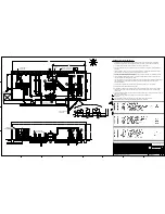
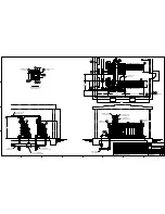
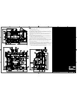
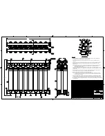
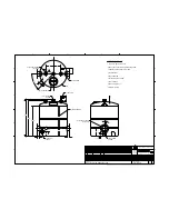
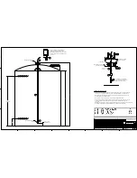
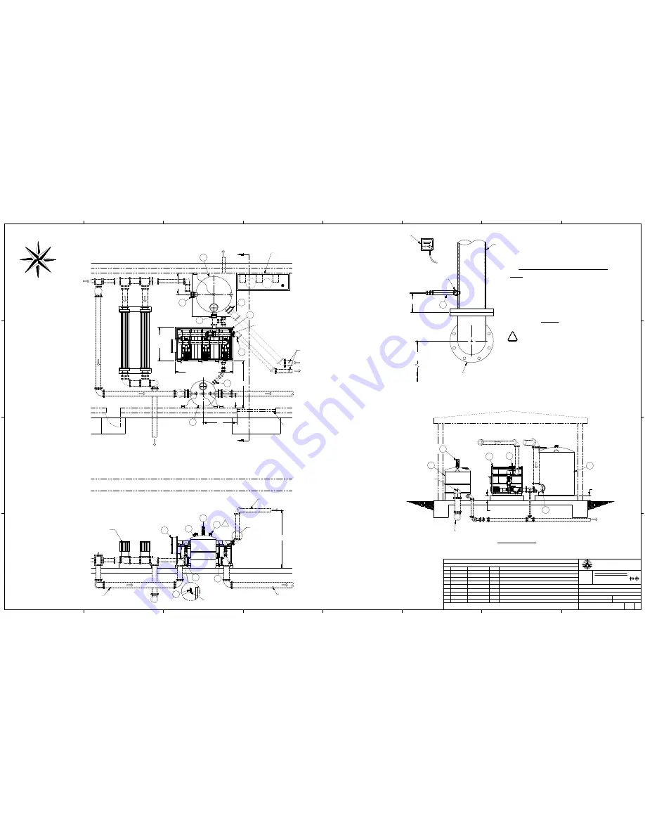
SYSTEM PLAN VIEW & GENERAL LIST
9107150D7000
1/48
GML
2013-12-02
3
5
AUGUSTA CORRECTIONAL FACILITY
CRAIGSVILLE, VIRGINIA
D
C16290
2014-05-19
AMG ITEM 34 WAS 2613574
C
C16217
2014-04-08
GML ADDED pH SENSOR (ITEM #35)
B
R14425
2014-04-02
GML RELEASE TO PRODUCTION
A
2013-12-02
GML SUBMITTAL RELEASE
S
W
E
N
12" TO N.P.W.P.S.
& POST AERATION
CHEMICAL FEED SYSTEM
(SUPPLIED BY OTHERS)
UV DISINFECTION
(SUPPLIED BY OTHERS)
12" FEED PIPING FROM
AQUADISK FILTER
12" FEED PIPING TO
MEMBRANE FEED SKIDS
8" BACKWASH PIPING TO
MEMBRANE FEED SKIDS
12" FEED PIPING TO
MEMBRANE FEED SKIDS
36
84
6
19
8
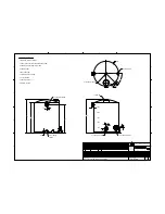
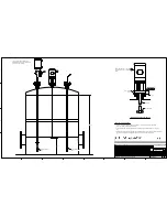
MIXER INSTALLATION
(MEMBRANE FEED)
1000 GALLON TANK
(MEMBRANE FEED)
3000 GALLON TANK
(PERMEATE HOLDING)
3
6
3
BACKWASH PUMP
SKID ASSEMBLY
19
3
6
8
117
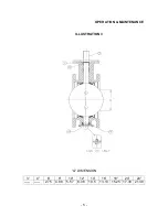
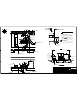
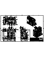
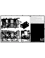
SECTION "A - A"
6" PIPING TO
DRAIN
6" PIPING TO
DRAIN
16
16
18
54
17
16
(12'-0")
17
16
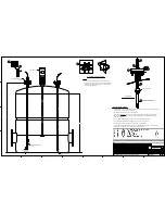
CHEMICAL INJECTION
POINTS (REF.)
SEE DETAIL "C"
MENU
ESC
ENTER
Thermo
SCIENTIFIC
AquaSensors
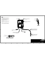
DETAIL "C" - pH SENSOR MOUNTING
NOTES:
1. THE CHEMICAL INJECTION POINTS HAVE BEEN RE-LOCATED
ONTO THE BACKWASH SKID.
2. pH SENSOR PROBE IS TO BE LOCATED IN A POSITION
ACCESSIBLE TO THE OPERATOR.
3. THE AV38 CONTROLLER WILL FACTORY MOUNTED ON THE
BACKWASH SKID ASSEMBLY (ITEM #3).
4. SENSOR CABLE MUST NOT BE CUT. COIL EXCESS LENGTH
TOGETHER AND ATTACH TO BACKWASH SKID (ITEM #3).
20
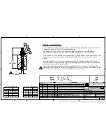
! ATTENTION:
THE BACKWASH PIPING MUST BE VENTED AND DRAINED
PRIOR TO REMOVING THE SENSOR FOR SERVICE OR
REPLACEMENT.
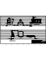
MANUAL AIR RELEASE
VALVES (SUPPLIED BY OTHERS)
8' WIDE x 10' TALL
ROLL UP DOOR (REF.)
1'-0" CONCRETE
PAD (REF.)
1'-0" CONCRETE
PAD (REF.)
(7'-0")
CONCRETE
PAD
(12'-0") CONCRETE
PAD
20
(63 11/16) TO
FINISH FLOOR
6
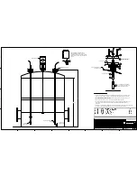
8" BACKWASH PIPING
(SUPPLIED BY OTHERS)
1" NPT HALF COUPLING
(SUPPLIED BY OTHERS)
8" 150# ANSI FLANGE
CONNECTION TO
BACKWASH SKID
AV38 CONTROLLER
(FACTORY MOUNTED
ON BACKWASH SKID)
1/4" SAMPLING PORT
AND VALVE (BY OTHERS)
A
A
1/4" NPT PORT (BY OTHERS)
FOR ALUM INJECTION
30
20
35
C
Summary of Contents for VG3B3-B
Page 14: ...GENERAL INFORMATION...
Page 17: ...EQUIPMENT SAFETY DOCUMENTS and PRECAUTIONS...
Page 30: ...U L MOTOR REQUIREMENTS...
Page 31: ......
Page 35: ...PROTECTIVE COATINGS...
Page 37: ...PAINT TECHNICAL DATA SHEETS...
Page 43: ...PASSIVATION DOCUMENTS...
Page 47: ...STORAGE PROCEDURES...
Page 51: ...INSTRUMENTATION...
Page 56: ...VALVES...
Page 58: ...PUMPS...
Page 61: ...MATERIAL SAFETY DATA SHEETS...
Page 65: ......
Page 66: ...PAINT COATING MSDS...
Page 73: ...ADHESIVE ANCHORS MSDS...
Page 74: ...SIMPSON...
Page 95: ......
Page 96: ......
Page 97: ......
Page 98: ......
Page 99: ......
Page 100: ...INSTALLATION AND START UP...
Page 103: ...START UP PAPERS...
Page 125: ...PROCESS AND CONTROL...
Page 181: ...MECHANICAL AND FIELD INSTRUMENT COMPONENT INFORMATION...
Page 182: ...ACTUATOR...
Page 183: ...CORD SET...
Page 185: ...AUMA...
Page 186: ...115V 1ph 60Hz...
Page 190: ...ANCHORS...
Page 191: ...ADHESIVE ANCHOR See Drawing Section 7 for Details...
Page 192: ...MANUAL GUN...
Page 194: ...REFILL PACK...
Page 197: ...MIXING NOZZLE...
Page 199: ...INSTRUMENTATION...
Page 200: ...CONTROLLER...
Page 201: ...THERMO FISHER...
Page 203: ...pH PROBE...
Page 206: ...FLOW METER...
Page 211: ...PRESSURE TRANSMITTER...
Page 213: ...PUMP...
Page 214: ...MEMBRANE FEED PUMP...
Page 217: ...Pump Part 2616713 Gorman Rupp VG3B3 B Centrifugal 2013 12 09 2616713 Pump doc 3 of 3...
Page 220: ...BACKWASH PUMP...
Page 223: ...Pump Part 2616695 Gorman Rupp VG3C3 B Centrifugal 2013 12 09 2616695 Pump doc 3 of 3...
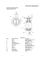
Page 227: ...BUTTERFLY VALVE...
Page 228: ...MANUAL LEVER BUTTERFLY VALVE...
Page 238: ...ELECTRIC BUTTERFLY VALVE...
Page 241: ...SWING CHECK VALVE...
Page 243: ...SOLENOID VALVE...
Page 245: ...MEMBRANE MODULE ACCESSORIES...
Page 254: ...AIR COMPRESSOR ACCESSORIES...
Page 258: ...ELECTRICAL CONTROL PANEL COMPONENT INFORMATION...
Page 265: ...CABLE CONDUIT WIRE...
Page 271: ...CIRCUIT BREAKER...
Page 281: ...COMPUTER and MONITOR...
Page 289: ...ENCLOSURE...
Page 296: ...ENCLOSURE ACCESSORIES...
Page 307: ...ENVIRONMENTAL CONTROL ENCLOSURE...
Page 314: ...FUSE...
Page 329: ...FUSE BLOCK...
Page 336: ...HMI HUMAN MACHINE INTERFACE...
Page 343: ...MAIN DISCONNECT...
Page 350: ...MAIN DISCONNECT ACCESSORIES...
Page 354: ...MOTOR CONTROL...
Page 368: ...NETWORK...
Page 379: ...PILOT DEVICE...
Page 392: ...PLC PROGRAMMABLE LOGIC CONTROL...
Page 420: ...PRINTERS...
Page 424: ...POWER SUPPLY...
Page 426: ...Power Supply Part 2751312 Allen Bradley 2008 02 28 2751312 AB Power Supply doc 2 of 5...
Page 427: ...Power Supply Part 2751312 Allen Bradley 2008 02 28 2751312 AB Power Supply doc 3 of 5...
Page 428: ...Power Supply Part 2751312 Allen Bradley 2008 02 28 2751312 AB Power Supply doc 4 of 5...
Page 429: ...Power Supply Part 2751312 Allen Bradley 2008 02 28 2751312 AB Power Supply doc 5 of 5...
Page 434: ...RELAY CONTROL...
Page 440: ...SURGE SUPPRESSOR TRANSIENT FILTER...
Page 447: ...TERMINAL BLOCK ACCESSORIES...
Page 471: ...TIMERS...
Page 477: ...TRANSFORMER ACCESSORIES...
Page 482: ...UPS UNINTERRUPTIBLE POWER SUPPLY...
Page 489: ...MAINTENANCE AND TROUBLESHOOTING...
Page 498: ...COMPONENT PRODUCTS EQUIPMENT O M INSTRUCTION MANUALS...
Page 499: ...ACTUATOR...
Page 500: ...ELECTRIC...
Page 534: ...ADHESIVE ANCHOR O M...
Page 535: ......
Page 537: ...INSTRUMENTATION O M...
Page 538: ...FLOW METER...
Page 684: ...5 NOTES 30 IFC 100 www krohne com 07 2010 4000124104 QS IFC 100 R04 en...
Page 685: ...NOTES 5 31 IFC 100 www krohne com 07 2010 4000124104 QS IFC 100 R04 en...
Page 687: ......
Page 688: ......
Page 689: ......
Page 690: ......
Page 691: ......
Page 692: ......
Page 693: ......
Page 694: ......
Page 695: ......
Page 696: ......
Page 697: ......
Page 698: ......
Page 699: ......
Page 700: ......
Page 701: ......
Page 702: ......
Page 703: ......
Page 704: ......
Page 705: ......
Page 706: ......
Page 707: ......
Page 708: ......
Page 709: ......
Page 710: ......
Page 711: ......
Page 712: ......
Page 713: ......
Page 714: ......
Page 715: ......
Page 716: ......
Page 717: ......
Page 718: ......
Page 719: ......
Page 720: ......
Page 721: ......
Page 722: ......
Page 723: ...TURBIDITY MONITORING O M...
Page 734: ...10 Installation Figure 4 1720E Dimensions...
Page 738: ...14 System Startup...
Page 746: ...22 Operation...
Page 754: ...30 Troubleshooting...
Page 760: ...36 Modbus Register Information...
Page 762: ...38 Index...
Page 763: ...DOC023 53 80221 FT660 sc 01 2012 Edition 2 User Manual...
Page 764: ......
Page 782: ...1 2 18 English...
Page 783: ...3 4 English 19...
Page 790: ...26 English...
Page 791: ......
Page 793: ...CONTROLLER...
Page 794: ...Thermo Scientific AquaSensors AV38 Local Display and Controller User Guide...
Page 873: ......
Page 875: ...pH PROBE...
Page 880: ...PRESSURE TRANSMITTER...
Page 881: ......
Page 900: ...A 9 Keller America Inc User s Guide Rev 10 11...
Page 901: ...A 10 Keller America Inc User s Guide Rev 10 11...
Page 904: ...MEMBRANE MODULE...
Page 905: ...inge GmbH Installation Operation and Maintenance Guidelines inge T Rack vario...
Page 934: ......
Page 935: ...Appendix B Process Specification inge UF...
Page 957: ...PUMPS...
Page 958: ...GORMAN RUPP PUMP...
Page 959: ......
Page 960: ......
Page 961: ......
Page 962: ......
Page 963: ......
Page 964: ......
Page 965: ......
Page 966: ......
Page 967: ......
Page 968: ......
Page 969: ......
Page 970: ......
Page 971: ......
Page 972: ......
Page 973: ......
Page 974: ......
Page 975: ......
Page 976: ......
Page 977: ......
Page 978: ......
Page 979: ......
Page 980: ......
Page 981: ......
Page 982: ......
Page 983: ......
Page 984: ......
Page 985: ......
Page 986: ......
Page 987: ......
Page 988: ......
Page 989: ......
Page 990: ......
Page 991: ......
Page 1056: ...VALVES...
Page 1057: ...NIBCO VALVE...
Page 1058: ...WAFER BUTTERFLY VALVE...
Page 1068: ...MILLIKEN VALVE...
Page 1069: ...MILLIKEN BUTTERFLY VALVE...
Page 1070: ......
Page 1077: ...MECHANICAL DRAWINGS...
Page 1110: ...ELECTRICAL DRAWINGS...
Page 1119: ......
Page 1153: ......
Page 1157: ......


