

-
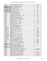
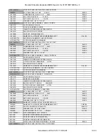
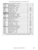
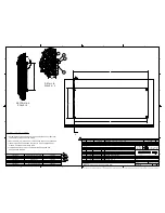
PLASTIC
COVER, UNISTRUT CHANNEL, 120" LG.
9107150D7082
3
55
-
BUNA
GROMMET, 11/16" ID
2606669
8
54
-
316 SS
HHCS, 1/4-20 X 0.75"
2603784
15
53
Y
304 SS
UNISTRUT CHANNEL 1-5/8" SQUARE x 66" LG.
9107150D7081
4
52
-
316 SS
NUT, HEX, #10-24
2609783
8
51
-
304 SS
WASHER, FLAT, #10 X .438" X .022"
2602131
8
50
-
316 SS
HHMS, #10-24 X 1.25IN LG.
2616551
4
49
-
Nylon-6/6
CORD GRIP, 0.169-0.449", 1/2" NPT STRAIGHT
2607535
4
48
-
ABS Plastic
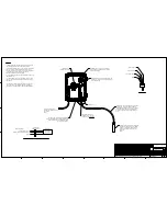
CONTROLLER & DISPLAY, THERMO SCIENTIFIC #AV38
2616180
1
47
-
PVC
CHECK VALVE, SPRING LOADED, BALL, 1/4 MNPT
2615634
3
46
-
PVC
RED BUSHING, 1/2" MNPT X 1/4" FNPT, S80
2613915
3
45
-
IRON, CAST
VALVE, CHECK, 3", FLANGED, F-918-B
2603743
3
44
Y
EPDM
GASKET, FULL FACE, 150#, 3"
2608363
3
43
-
VALVE, 4", BFLY, NIBCO, WAFER, W / LEVER
2612365
3
42
-
-
WIRE, 10 GA., 19STR, 600V, THHN, GREEN
2612662
10 FT.
41
-
-
WIRE, 10 GA., 19STR, 600V, THHN, BLACK
2612661
50 FT.
40
-
-
CABLE, ELECTRIC, #16-3 COND., COLEMAN #22326
2616644
30 FT.
39
-
-
CORDGRIP, 0.169 - 0.499, 1/2" NPT
2607535
2
38
-
-
CABLE, SHIELDED TWISTED PAIR, BELDEN 3088AE
2752629
60 FT.
37
-
PVC
FLEX CONDUIT, PVC, 1", BLACK
2612061
10 FT.
36
-
NYLON
CONNECTOR, STRAIGHT, FLEX CONDUIT, 1"
2612060
3
35
-
NYLON
CONNECTOR, 90DEG, FLEX CONDUIT, 1"
2616708
3
34
-
316 SS
NUT, HEX, JAM, 1/4-20
2603011
9
33
-
316 SS
NUT, HEX, FULL, 1/4-20
2600476
9
32
-
316 SS
WASHER, FLAT, 1/4" X 5/8" X .044"
2600224
33
31
-
316 SS
HHCS, 1/4-20 X 1"
2600230
9
30
-
-
ELECTRIC DISCONNECT, 60A, NEMA 3R
2752669
3
29
-
316 SS
HHCS, 3/8-16 X 1.5"
2600421
4
28
Y
FIBERGLASS
INSTL, CONTROL PANEL, BACKWASH SKID
9107150D7702
1
27
-
316 SS
RING, 8" KROHNE GROUNDING
2612314
2
26
Y
MILD STEEL
WELDMENT, PIPE SUPPORT, 8" PIPE
9107150D7027
3
25
-
316 SS
HHCS, 3/8-16 X 1.25"
2602257
18
24
-
316 SS
NUT, HEX, JAM, 3/8-16
2600403
44
23
-
316 SS
NUT, HEX, FULL, 3/8-16
2600481
44
22
-
316 SS
WASHER, FLAT, 3/8" X 1" X .042"
2600381
66
21
Y
304 SS
U-BOLT, 3/8"-16 X 8" PIPE
2609993
11
20
-
316 SS
NUT, HEX, JAM, 3/4-10
2602579
16
19
-
316 SS
NUT, HEX, FULL, 3/4-10
2600496
16
18
-
304 SS
HHCS, 3/4-10 X 4.5"
2605196
16
17
-
316 SS
WASHER, FLAT, 3/4" X 1 7/8"
2602580
32
16
Y
EPDM
GASKET, FULL FACE, 150#, 8"
2510129
4
15
-
304 SS
HHCS, 5/8-11 X 6.00"
2603802
24
14
-
316 SS
HHCS, 5/8-11 X 5.50"
2605981
12
13
-
316 SS
NUT, HEX, JAM, 5/8-11
2600302
60
12
-
316 SS
NUT, HEX, FULL, 5/8-11
2600301
60
11
-
304 SS
HHCS, 5/8-11 X 3.25"
2605722
24
10
-
316 SS
WASHER, FLAT, 5/8" X 1 1/4"
2602498
120
9
-
304 SS
EXPANSION JOINT, 3", 150#, METRASPHERE
2616073
3
8
Y
PVC
ASSEMBLY, FLANGED PIPE, 8" SCH 80 x 50.75"
9107150D7026
1
7
-
-
VALVE, NIBCO, 3", BUTTERFLY
2612364
3
6
-
-
FLOW METER, 8" CONVERTER 110V
2612115
1
5
Y
PVC
ASSEMBLY, PIPING, DISCHARGE MANIFOLD
9107150D7016
1
4
Y
PVC
ASSEMBLY, PIPING, INLET MANIFOLD, BACKWASH SKID
9107150D7015
1
3
Y
-
ASSEMBLY, PUMP, G-R, VG3C3-B, 20 HP
2967005-2
3
2
Y
MILD STEEL
WELDMENT, BASE FRAME, BACKWASH PUMP
9107150D7010
1
1
DWG
MATERIAL
DESCRIPTION
PART NUMBER
QTY
ITEM
1
1
2
2
3
3
4
4
5
5
6
6
7
7
8
8
A
A
B
B
C
C
D
D
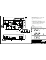
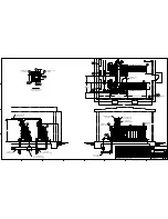
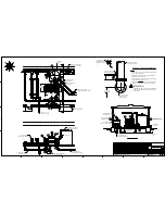
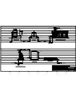
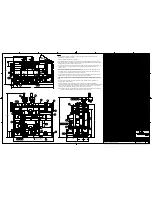
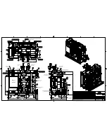
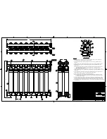
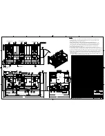
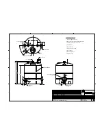
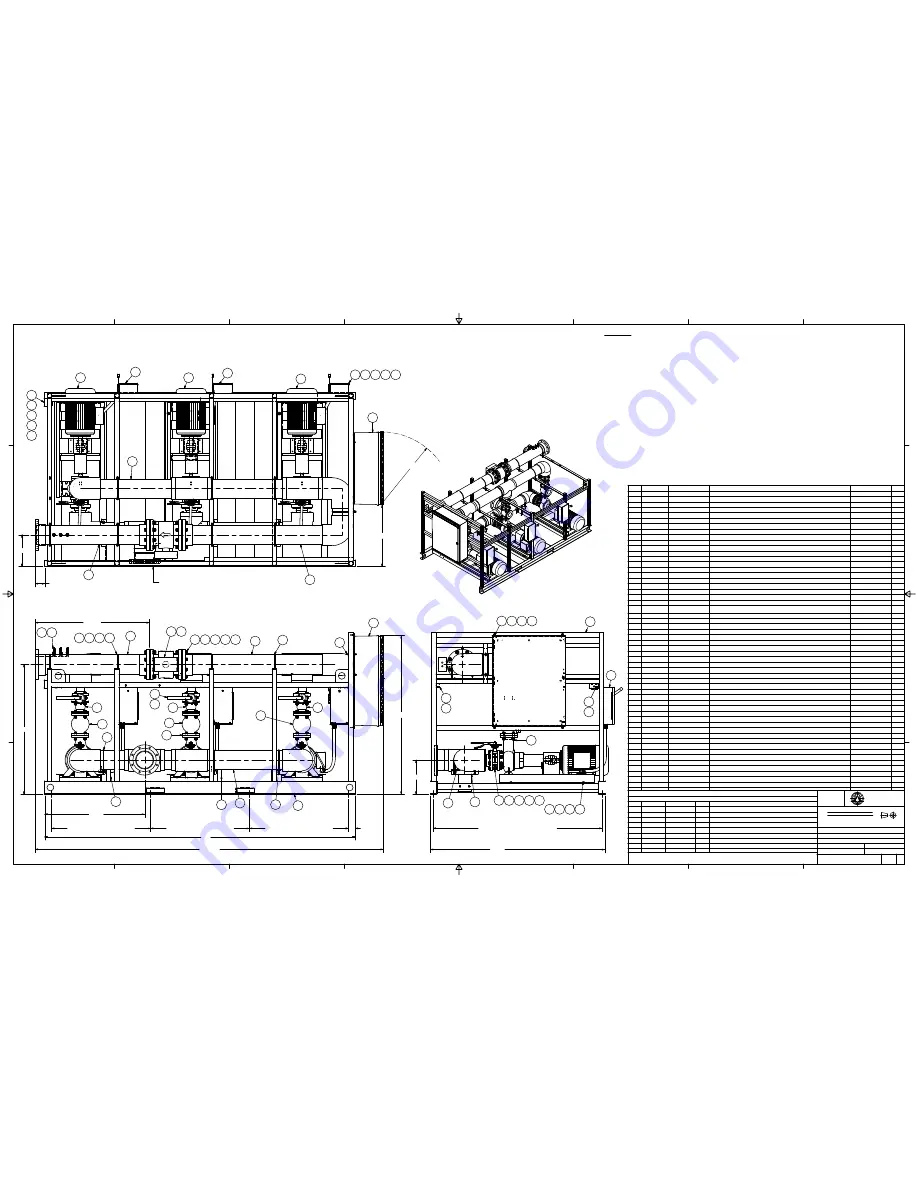
ASSEMBLY, BACKWASH PUMP SKID
COPYRIGHT 2013 AQUA-AEROBIC SYSTEMS, INC. ALL RIGHTS RESERVED. THIS DRAWING MAY NOT BE COPIED ALL OR IN PART WITHOUT THE EXPRESS WRITTEN PERMISSION OF AQUA-AEROBIC SYSTEMS, INC.
ANSI
D
JOB NAME:
JOB LOCATION:
DRAWING NAME:
DRAWING NUMBER:
WEIGHT:
TYPE:
SIMILAR TO:
MATERIAL:
SHEET:
OF
SIZE:
SCALE:
9107150D7003
4000
1/12
AUGUSTA CORRECTIONAL FACILITY
CRAIGSVILLE, VIRGINIA
DRAWN BY:
DATE:
GML
2013-11-07
LBS
UNLESS OTHERWISE SPECIFIED
ALL DIMENSIONS ARE IN INCHES
DO NOT
SCALE
DRAWING
AQUA-AEROBIC
SYSTEMS, INC.
+/- 1/16
+/- 0.010
+/- 0.005
+/- 1/2
FRACTIONAL DIMENSIONS
ALL TWO PLACE DECIMALS
ALL THREE PLACE DECIMALS
ALL ANGLES
1
1
A
2013-11-19
GML SUBMITTAL RELEASE
B
R14425
2014-04-02
GML RELEASE TO PRODUCTION
REV
ERN/ECO
DATE
BY
REVISION DESCRIPTION
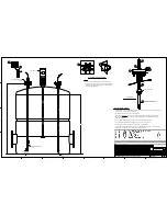
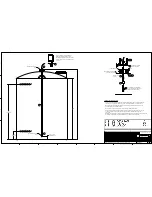
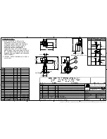
NOTES:
1. ANTI-SEIZE LUBRICANT IS REQUIRED ON ALL STAINLESS STEEL FASTENERS, UNLESS OTHERWISE SPECIFIED.
2. SHIELDED CABLE (ITEM #37), CORDGRIP (ITEM #38) AND #16-3 CONDUCTOR ELECTRIC CABLE (ITEM #39) ARE
TO BE USED FOR WIRING TO THE FLOW METER (ITEM #5).
3. 90 DEGREE CONDUIT CONNECTOR (ITEM #34) IS TO BE USED AT THE PUMP MOTOR JUNCTION BOX. STRAIGHT
CONDUIT CONNECTOR (ITEM #35) IS TO BE USED AT THE DISCONNECT BOX (ITEM #29) PROVIDED.
4. USE 10 GA. WIRE (ITEM #40 AND #41) TO WIRE PUMP MOTORS TO DISCONNECT BOXES. BLACK WIRE (ITEM #40)
IS TO BE USED FOR THE MOTOR WINDINGS. GREEN WIRE (ITEM #41) IS TO BE USED AS THE GROUND WIRE.
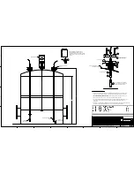
5. #16-3 CONDUCTOR CABLE (ITEM #39) IS TO BE USED AS A POWER WIRE BETWEEN THE AV38 CONTROLLER
(ITEM #47) AND THE CONTROL PANEL (ITEM #27).
6. THERE WILL BE TWO LENGTHS OF THE SHIELDED CABLE (ITEM #37) FROM THE AV38 CONTROLLER (ITEM #47) TO
THE CONTROL PANEL (ITEM #27). ONE LENGTH IS FOR THE pH SIGNAL AND THE OTHER IS FOR THE TEMPERATURE SIGNAL.
7. THE BACK OF THE CONTROLLER (ITEM #47) MAY NEED TO HAVE THE MOUNTING HOLES FACTORY PUNCHED OR DRILLED.
8. DRILL AND TAP 1/4"-20UNC HOLES IN FRAME WELDMENT (ITEM #1) FOR MOUNTING UNISTRUT CHANNEL (ITEM #52) DURING
ASSEMBLY. USE 1/4" HARDWARE (ITEM #53 AND #31) FOR MOUNTING. INSERT GROMMETS (ITEM #54) IN HOLES IN
UNISTRUT FOR ROUTING CABLES. CUT UNISTRUT CHANNEL COVER (ITEM #55) TO LENGTH AS NECESSARY AND INSTALL
AFTER ROUTING CABLES.
NOTE:
WHEN ROUTING POWER CABLES AND SIGNAL CABLES THROUGH THE SAME CHANNEL A DIVIDER MUST BE USED
TO KEEP THE POWER CABLES SEPARATED FROM THE SIGNAL CABLE.
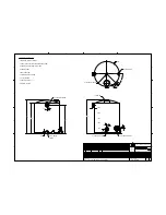
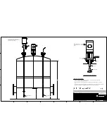
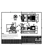
(70 9/16)
138
44 3/8
15 1/4
77 1/2
42
9
11
12
14
1
2
2
2
29
4
5
26
17
15
16
18
19
27
29
30
31
32
33
27
28
21
22
23
3
1
29
29
4
7
4
20
21
22
23
3
8
8
8
25
25
25
25
24
21
22
23
20
20
20
6
13
44
43
44
44
7
14 1/8
46
45
47
48
49
50
51
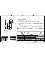
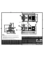
BWCP
52
55
52
55
MTR-202
MTR-222
MTR-242
BACKWASH PUMP NO. 1
BACKWASH PUMP NO. 2
BACKWASH PUMP NO. 3
DS-202
DS-222
DS-242
75 TO CENTERLINE OF ANCHORS
44 CENTERLINE OF ANCHOR
44 CENTERLINE OF ANCHOR
44 CENTERLINE OF ANCHOR
3
FIT-316
10
4 1/4 TO FACE
OF DISCHARGE
FLANGE
1 5/8 TO FACE OF
INLET FLANGE
(50 3/4)
(R32 1/2)
(27 3/8)
57 11/16
(154 3/4)
Summary of Contents for VG3B3-B
Page 14: ...GENERAL INFORMATION...
Page 17: ...EQUIPMENT SAFETY DOCUMENTS and PRECAUTIONS...
Page 30: ...U L MOTOR REQUIREMENTS...
Page 31: ......
Page 35: ...PROTECTIVE COATINGS...
Page 37: ...PAINT TECHNICAL DATA SHEETS...
Page 43: ...PASSIVATION DOCUMENTS...
Page 47: ...STORAGE PROCEDURES...
Page 51: ...INSTRUMENTATION...
Page 56: ...VALVES...
Page 58: ...PUMPS...
Page 61: ...MATERIAL SAFETY DATA SHEETS...
Page 65: ......
Page 66: ...PAINT COATING MSDS...
Page 73: ...ADHESIVE ANCHORS MSDS...
Page 74: ...SIMPSON...
Page 95: ......
Page 96: ......
Page 97: ......
Page 98: ......
Page 99: ......
Page 100: ...INSTALLATION AND START UP...
Page 103: ...START UP PAPERS...
Page 125: ...PROCESS AND CONTROL...
Page 181: ...MECHANICAL AND FIELD INSTRUMENT COMPONENT INFORMATION...
Page 182: ...ACTUATOR...
Page 183: ...CORD SET...
Page 185: ...AUMA...
Page 186: ...115V 1ph 60Hz...
Page 190: ...ANCHORS...
Page 191: ...ADHESIVE ANCHOR See Drawing Section 7 for Details...
Page 192: ...MANUAL GUN...
Page 194: ...REFILL PACK...
Page 197: ...MIXING NOZZLE...
Page 199: ...INSTRUMENTATION...
Page 200: ...CONTROLLER...
Page 201: ...THERMO FISHER...
Page 203: ...pH PROBE...
Page 206: ...FLOW METER...
Page 211: ...PRESSURE TRANSMITTER...
Page 213: ...PUMP...
Page 214: ...MEMBRANE FEED PUMP...
Page 217: ...Pump Part 2616713 Gorman Rupp VG3B3 B Centrifugal 2013 12 09 2616713 Pump doc 3 of 3...
Page 220: ...BACKWASH PUMP...
Page 223: ...Pump Part 2616695 Gorman Rupp VG3C3 B Centrifugal 2013 12 09 2616695 Pump doc 3 of 3...
Page 227: ...BUTTERFLY VALVE...
Page 228: ...MANUAL LEVER BUTTERFLY VALVE...
Page 238: ...ELECTRIC BUTTERFLY VALVE...
Page 241: ...SWING CHECK VALVE...
Page 243: ...SOLENOID VALVE...
Page 245: ...MEMBRANE MODULE ACCESSORIES...
Page 254: ...AIR COMPRESSOR ACCESSORIES...
Page 258: ...ELECTRICAL CONTROL PANEL COMPONENT INFORMATION...
Page 265: ...CABLE CONDUIT WIRE...
Page 271: ...CIRCUIT BREAKER...
Page 281: ...COMPUTER and MONITOR...
Page 289: ...ENCLOSURE...
Page 296: ...ENCLOSURE ACCESSORIES...
Page 307: ...ENVIRONMENTAL CONTROL ENCLOSURE...
Page 314: ...FUSE...
Page 329: ...FUSE BLOCK...
Page 336: ...HMI HUMAN MACHINE INTERFACE...
Page 343: ...MAIN DISCONNECT...
Page 350: ...MAIN DISCONNECT ACCESSORIES...
Page 354: ...MOTOR CONTROL...
Page 368: ...NETWORK...
Page 379: ...PILOT DEVICE...
Page 392: ...PLC PROGRAMMABLE LOGIC CONTROL...
Page 420: ...PRINTERS...
Page 424: ...POWER SUPPLY...
Page 426: ...Power Supply Part 2751312 Allen Bradley 2008 02 28 2751312 AB Power Supply doc 2 of 5...
Page 427: ...Power Supply Part 2751312 Allen Bradley 2008 02 28 2751312 AB Power Supply doc 3 of 5...
Page 428: ...Power Supply Part 2751312 Allen Bradley 2008 02 28 2751312 AB Power Supply doc 4 of 5...
Page 429: ...Power Supply Part 2751312 Allen Bradley 2008 02 28 2751312 AB Power Supply doc 5 of 5...
Page 434: ...RELAY CONTROL...
Page 440: ...SURGE SUPPRESSOR TRANSIENT FILTER...
Page 447: ...TERMINAL BLOCK ACCESSORIES...
Page 471: ...TIMERS...
Page 477: ...TRANSFORMER ACCESSORIES...
Page 482: ...UPS UNINTERRUPTIBLE POWER SUPPLY...
Page 489: ...MAINTENANCE AND TROUBLESHOOTING...
Page 498: ...COMPONENT PRODUCTS EQUIPMENT O M INSTRUCTION MANUALS...
Page 499: ...ACTUATOR...
Page 500: ...ELECTRIC...
Page 534: ...ADHESIVE ANCHOR O M...
Page 535: ......
Page 537: ...INSTRUMENTATION O M...
Page 538: ...FLOW METER...
Page 684: ...5 NOTES 30 IFC 100 www krohne com 07 2010 4000124104 QS IFC 100 R04 en...
Page 685: ...NOTES 5 31 IFC 100 www krohne com 07 2010 4000124104 QS IFC 100 R04 en...
Page 687: ......
Page 688: ......
Page 689: ......
Page 690: ......
Page 691: ......
Page 692: ......
Page 693: ......
Page 694: ......
Page 695: ......
Page 696: ......
Page 697: ......
Page 698: ......
Page 699: ......
Page 700: ......
Page 701: ......
Page 702: ......
Page 703: ......
Page 704: ......
Page 705: ......
Page 706: ......
Page 707: ......
Page 708: ......
Page 709: ......
Page 710: ......
Page 711: ......
Page 712: ......
Page 713: ......
Page 714: ......
Page 715: ......
Page 716: ......
Page 717: ......
Page 718: ......
Page 719: ......
Page 720: ......
Page 721: ......
Page 722: ......
Page 723: ...TURBIDITY MONITORING O M...
Page 734: ...10 Installation Figure 4 1720E Dimensions...
Page 738: ...14 System Startup...
Page 746: ...22 Operation...
Page 754: ...30 Troubleshooting...
Page 760: ...36 Modbus Register Information...
Page 762: ...38 Index...
Page 763: ...DOC023 53 80221 FT660 sc 01 2012 Edition 2 User Manual...
Page 764: ......
Page 782: ...1 2 18 English...
Page 783: ...3 4 English 19...
Page 790: ...26 English...
Page 791: ......
Page 793: ...CONTROLLER...
Page 794: ...Thermo Scientific AquaSensors AV38 Local Display and Controller User Guide...
Page 873: ......
Page 875: ...pH PROBE...
Page 880: ...PRESSURE TRANSMITTER...
Page 881: ......
Page 900: ...A 9 Keller America Inc User s Guide Rev 10 11...
Page 901: ...A 10 Keller America Inc User s Guide Rev 10 11...
Page 904: ...MEMBRANE MODULE...
Page 905: ...inge GmbH Installation Operation and Maintenance Guidelines inge T Rack vario...
Page 934: ......
Page 935: ...Appendix B Process Specification inge UF...
Page 957: ...PUMPS...
Page 958: ...GORMAN RUPP PUMP...
Page 959: ......
Page 960: ......
Page 961: ......
Page 962: ......
Page 963: ......
Page 964: ......
Page 965: ......
Page 966: ......
Page 967: ......
Page 968: ......
Page 969: ......
Page 970: ......
Page 971: ......
Page 972: ......
Page 973: ......
Page 974: ......
Page 975: ......
Page 976: ......
Page 977: ......
Page 978: ......
Page 979: ......
Page 980: ......
Page 981: ......
Page 982: ......
Page 983: ......
Page 984: ......
Page 985: ......
Page 986: ......
Page 987: ......
Page 988: ......
Page 989: ......
Page 990: ......
Page 991: ......
Page 1056: ...VALVES...
Page 1057: ...NIBCO VALVE...
Page 1058: ...WAFER BUTTERFLY VALVE...
Page 1068: ...MILLIKEN VALVE...
Page 1069: ...MILLIKEN BUTTERFLY VALVE...
Page 1070: ......
Page 1077: ...MECHANICAL DRAWINGS...
Page 1110: ...ELECTRICAL DRAWINGS...
Page 1119: ......
Page 1153: ......
Page 1157: ......


