

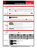
HI-BUILD EPOXOLINE II
PRODUCT DATA SHEET
N69 or V69
PRODUCT PROFILE
GENERIC DESCRIPTION
Polyamidoamine Epoxy
COMMON USAGE
An advanced generation epoxy for protection and finishing of steel and concrete. It has excellent resistance to abrasion
and is suitable for immersion as well as chemical contact exposure. Contact your local Tnemec representative for a list of
chemicals. This product can also be used for lining storage tanks that contain demineralized, deionized or distilled water.
Note: Series V69 conforms with air pollution regulations limiting Volatile Organic Compounds (VOC) to a maximum of
250 grams/litre (2.08 lbs/gal) in areas requiring less than 100 grams/litre VOC, please refer to the Series L69 data sheet.
COLORS
Refer to Tnemec Color Guide. Note: Epoxies chalk with extended exposure to sunlight. Lack of ventilation, incomplete
mixing, miscatalyzation or the use of heaters that emit carbon dioxide and carbon monoxide during application and initial
stages of curing may cause yellowing to occur.
FINISH
Satin
SPECIAL QUALIFICATIONS
A two-coat system at 4.0-6.0 dry mills (100-150 dry microns) per coat passes the performance requirements of MIL-PRF-
4556F for fuel storage.
PERFORMANCE CRITERIA
Extensive test data available. Contact your Tnemec representative for specific test results.
Published technical data and instructions are subject to change without notice. The online catalog at www.tnemec.com
should be referenced for the most current technical data and instructions or you may contact your Tnemec representative
for current technical data and instructions.
© May 14, 2010 by Tnemec Co., Inc.
COATING SYSTEM
PRIMERS
Steel: Self-priming or Series 1, 27, 37H, 66, 90E-92, 90-97, 90-1K97, 91-H
2
O, 94-H
2
O, 135, 161, 394, 530
Galvanized Steel and Non-Ferrous Metal: Self-priming or Series 66, 161
Concrete: Self-priming or Series 130, 218
CMU: Self-priming or 54-562, 130, 215, 216, 218
TOPCOATS
46H-413, 66, L69, N69, 73, 84, 104, 113, 114, 161, 175, 1028, 1029, 1070, 1071, 1072, 1074, 1074U, 1075, 1075U, 1077,
1078. Refer to COLORS on applicable topcoat data sheets for additional information. Note: The following recoat times
apply for Series N69/V69: Immersion Service—Surface must be scarified after 60 days. Atmospheric Service—After 60
days, scarification or an epoxy tie-coat is required. Contact your Tnemec representative for specific recommendations.
Published technical data and instructions are subject to change without notice. The online catalog at www.tnemec.com
should be referenced for the most current technical data and instructions or you may contact your Tnemec representative
for current technical data and instructions.
SURFACE PREPARATION
PRIMED STEEL
Immersion Service: Scarify the Series 66, N69/V69 or 161 prime coat surface by abrasive blasting with fine abrasive before
topcoating if it has been exterior exposed for 60 days or longer and N69/V69 is the specified topcoat.
STEEL
Immersion Service: SSPC-SP10/NACE 2 Near-White Blast Cleaning
Non-Immersion Service: SSPC-SP6/NACE 3 Commercial Blast Cleaning
GALVANIZED STEEL & NON-
FERROUS METAL
Surface preparation recommendations will vary depending on substrate and exposure conditions. Contact your Tnemec
representative or Tnemec Technical Services.
CAST/DUCTILE IRON
Contact your Tnemec representative or Tnemec Technical Services.
CONCRETE
Allow new concrete to cure 28 days. For optimum results and/or immersion service, abrasive blast referencing SSPC-
SP13/NACE 6, ICRI CSP 2-4 Surface Preparation of Concrete and Tnemec’s Surface Preparation and Application Guide.
CMU
Allow mortar to cure for 28 days. Level protrusions and mortar spatter.
PAINTED SURFACES
Non-Immersion Service: Ask your Tnemec representative for specific recommendations.
ALL SURFACES
Must be clean, dry and free of oil, grease, chalk and other contaminants.
Published technical data and instructions are subject to change without notice. The online catalog at www.tnemec.com
should be referenced for the most current technical data and instructions or you may contact your Tnemec representative
for current technical data and instructions.
TECHNICAL DATA
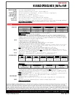
VOLUME SOLIDS
67.0 ± 2.0% (mixed) †
RECOMMENDED DFT
2.0 to 10.0 mils (50 to 255 microns) per coat. Note: MIL-PRF-4556F applications require two coats at 4.0-6.0 mils (100-150
microns) per coat. Otherwise, the number of coats and thickness requirements will vary with substrate, application
method and exposure. Contact your Tnemec representative.
CURING TIME AT 5 MILS DFT
Without 44-700 Accelerator
Temperature
To Handle
To Recoat
Immersion
90°F (32°C)
4 hours
7 hours
6 days
80°F (27°C)
5 hours
8 hours
7 days
70°F (21°C)
7 hours
10 hours
7 days
60°F (16°C)
8 hours
12 hours
9 days
50°F (10°C)
12 hours
16 hours
12 days
Curing time varies with surface temperature, air movement, humidity and film thickness. Note: For faster curing and low-
temperature applications, add No. 44-700 Epoxy Accelerator; see separate product data sheet.
VOLITILE ORGANIC COMPOUNDS
N69 - Unthinned: 2.40 lbs/gallon (285 grams/litre)
Thinned 10% (No. 4 Thinner): 2.80 lbs/gallon (334 grams/litre)
Thinned 10% (No. 60 Thinner): 2.80 lbs/gallon (335 grams/litre)
V69 - Unthinned: 1.95 lbs/gallon (234 grams/litre)
Thinned 2.5%: 2.08 lbs/gallon (250 grams/litre) †
HAPS
N69 - Unthinned: 2.40 lbs/gal solids
Thinned 10% (No. 4 Thinner): 3.25 lbs/gal solids
Thinned 10% (No. 60 Thinner): 2.40 lbs/gal solids
V69 - Unthinned: 2.05 lbs/gal solids
Thinned 2.5%: 2.30 lbs/gal solids)
THEORETICAL COVERAGE
1,074 mil sq ft/gal (26.4 m²/L at 25 microns). See APPLICATION for coverage rates. †
Page 1 of 2
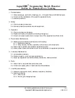
Summary of Contents for VG3B3-B
Page 14: ...GENERAL INFORMATION...
Page 17: ...EQUIPMENT SAFETY DOCUMENTS and PRECAUTIONS...
Page 30: ...U L MOTOR REQUIREMENTS...
Page 31: ......
Page 35: ...PROTECTIVE COATINGS...
Page 37: ...PAINT TECHNICAL DATA SHEETS...
Page 43: ...PASSIVATION DOCUMENTS...
Page 47: ...STORAGE PROCEDURES...
Page 51: ...INSTRUMENTATION...
Page 56: ...VALVES...
Page 58: ...PUMPS...
Page 61: ...MATERIAL SAFETY DATA SHEETS...
Page 65: ......
Page 66: ...PAINT COATING MSDS...
Page 73: ...ADHESIVE ANCHORS MSDS...
Page 74: ...SIMPSON...
Page 95: ......
Page 96: ......
Page 97: ......
Page 98: ......
Page 99: ......
Page 100: ...INSTALLATION AND START UP...
Page 103: ...START UP PAPERS...
Page 125: ...PROCESS AND CONTROL...
Page 181: ...MECHANICAL AND FIELD INSTRUMENT COMPONENT INFORMATION...
Page 182: ...ACTUATOR...
Page 183: ...CORD SET...
Page 185: ...AUMA...
Page 186: ...115V 1ph 60Hz...
Page 190: ...ANCHORS...
Page 191: ...ADHESIVE ANCHOR See Drawing Section 7 for Details...
Page 192: ...MANUAL GUN...
Page 194: ...REFILL PACK...
Page 197: ...MIXING NOZZLE...
Page 199: ...INSTRUMENTATION...
Page 200: ...CONTROLLER...
Page 201: ...THERMO FISHER...
Page 203: ...pH PROBE...
Page 206: ...FLOW METER...
Page 211: ...PRESSURE TRANSMITTER...
Page 213: ...PUMP...
Page 214: ...MEMBRANE FEED PUMP...
Page 217: ...Pump Part 2616713 Gorman Rupp VG3B3 B Centrifugal 2013 12 09 2616713 Pump doc 3 of 3...
Page 220: ...BACKWASH PUMP...
Page 223: ...Pump Part 2616695 Gorman Rupp VG3C3 B Centrifugal 2013 12 09 2616695 Pump doc 3 of 3...
Page 227: ...BUTTERFLY VALVE...
Page 228: ...MANUAL LEVER BUTTERFLY VALVE...
Page 238: ...ELECTRIC BUTTERFLY VALVE...
Page 241: ...SWING CHECK VALVE...
Page 243: ...SOLENOID VALVE...
Page 245: ...MEMBRANE MODULE ACCESSORIES...
Page 254: ...AIR COMPRESSOR ACCESSORIES...
Page 258: ...ELECTRICAL CONTROL PANEL COMPONENT INFORMATION...
Page 265: ...CABLE CONDUIT WIRE...
Page 271: ...CIRCUIT BREAKER...
Page 281: ...COMPUTER and MONITOR...
Page 289: ...ENCLOSURE...
Page 296: ...ENCLOSURE ACCESSORIES...
Page 307: ...ENVIRONMENTAL CONTROL ENCLOSURE...
Page 314: ...FUSE...
Page 329: ...FUSE BLOCK...
Page 336: ...HMI HUMAN MACHINE INTERFACE...
Page 343: ...MAIN DISCONNECT...
Page 350: ...MAIN DISCONNECT ACCESSORIES...
Page 354: ...MOTOR CONTROL...
Page 368: ...NETWORK...
Page 379: ...PILOT DEVICE...
Page 392: ...PLC PROGRAMMABLE LOGIC CONTROL...
Page 420: ...PRINTERS...
Page 424: ...POWER SUPPLY...
Page 426: ...Power Supply Part 2751312 Allen Bradley 2008 02 28 2751312 AB Power Supply doc 2 of 5...
Page 427: ...Power Supply Part 2751312 Allen Bradley 2008 02 28 2751312 AB Power Supply doc 3 of 5...
Page 428: ...Power Supply Part 2751312 Allen Bradley 2008 02 28 2751312 AB Power Supply doc 4 of 5...
Page 429: ...Power Supply Part 2751312 Allen Bradley 2008 02 28 2751312 AB Power Supply doc 5 of 5...
Page 434: ...RELAY CONTROL...
Page 440: ...SURGE SUPPRESSOR TRANSIENT FILTER...
Page 447: ...TERMINAL BLOCK ACCESSORIES...
Page 471: ...TIMERS...
Page 477: ...TRANSFORMER ACCESSORIES...
Page 482: ...UPS UNINTERRUPTIBLE POWER SUPPLY...
Page 489: ...MAINTENANCE AND TROUBLESHOOTING...
Page 498: ...COMPONENT PRODUCTS EQUIPMENT O M INSTRUCTION MANUALS...
Page 499: ...ACTUATOR...
Page 500: ...ELECTRIC...
Page 534: ...ADHESIVE ANCHOR O M...
Page 535: ......
Page 537: ...INSTRUMENTATION O M...
Page 538: ...FLOW METER...
Page 684: ...5 NOTES 30 IFC 100 www krohne com 07 2010 4000124104 QS IFC 100 R04 en...
Page 685: ...NOTES 5 31 IFC 100 www krohne com 07 2010 4000124104 QS IFC 100 R04 en...
Page 687: ......
Page 688: ......
Page 689: ......
Page 690: ......
Page 691: ......
Page 692: ......
Page 693: ......
Page 694: ......
Page 695: ......
Page 696: ......
Page 697: ......
Page 698: ......
Page 699: ......
Page 700: ......
Page 701: ......
Page 702: ......
Page 703: ......
Page 704: ......
Page 705: ......
Page 706: ......
Page 707: ......
Page 708: ......
Page 709: ......
Page 710: ......
Page 711: ......
Page 712: ......
Page 713: ......
Page 714: ......
Page 715: ......
Page 716: ......
Page 717: ......
Page 718: ......
Page 719: ......
Page 720: ......
Page 721: ......
Page 722: ......
Page 723: ...TURBIDITY MONITORING O M...
Page 734: ...10 Installation Figure 4 1720E Dimensions...
Page 738: ...14 System Startup...
Page 746: ...22 Operation...
Page 754: ...30 Troubleshooting...
Page 760: ...36 Modbus Register Information...
Page 762: ...38 Index...
Page 763: ...DOC023 53 80221 FT660 sc 01 2012 Edition 2 User Manual...
Page 764: ......
Page 782: ...1 2 18 English...
Page 783: ...3 4 English 19...
Page 790: ...26 English...
Page 791: ......
Page 793: ...CONTROLLER...
Page 794: ...Thermo Scientific AquaSensors AV38 Local Display and Controller User Guide...
Page 873: ......
Page 875: ...pH PROBE...
Page 880: ...PRESSURE TRANSMITTER...
Page 881: ......
Page 900: ...A 9 Keller America Inc User s Guide Rev 10 11...
Page 901: ...A 10 Keller America Inc User s Guide Rev 10 11...
Page 904: ...MEMBRANE MODULE...
Page 905: ...inge GmbH Installation Operation and Maintenance Guidelines inge T Rack vario...
Page 934: ......
Page 935: ...Appendix B Process Specification inge UF...
Page 957: ...PUMPS...
Page 958: ...GORMAN RUPP PUMP...
Page 959: ......
Page 960: ......
Page 961: ......
Page 962: ......
Page 963: ......
Page 964: ......
Page 965: ......
Page 966: ......
Page 967: ......
Page 968: ......
Page 969: ......
Page 970: ......
Page 971: ......
Page 972: ......
Page 973: ......
Page 974: ......
Page 975: ......
Page 976: ......
Page 977: ......
Page 978: ......
Page 979: ......
Page 980: ......
Page 981: ......
Page 982: ......
Page 983: ......
Page 984: ......
Page 985: ......
Page 986: ......
Page 987: ......
Page 988: ......
Page 989: ......
Page 990: ......
Page 991: ......
Page 1056: ...VALVES...
Page 1057: ...NIBCO VALVE...
Page 1058: ...WAFER BUTTERFLY VALVE...
Page 1068: ...MILLIKEN VALVE...
Page 1069: ...MILLIKEN BUTTERFLY VALVE...
Page 1070: ......
Page 1077: ...MECHANICAL DRAWINGS...
Page 1110: ...ELECTRICAL DRAWINGS...
Page 1119: ......
Page 1153: ......
Page 1157: ......