

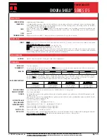
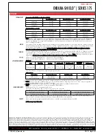

APPLICATION
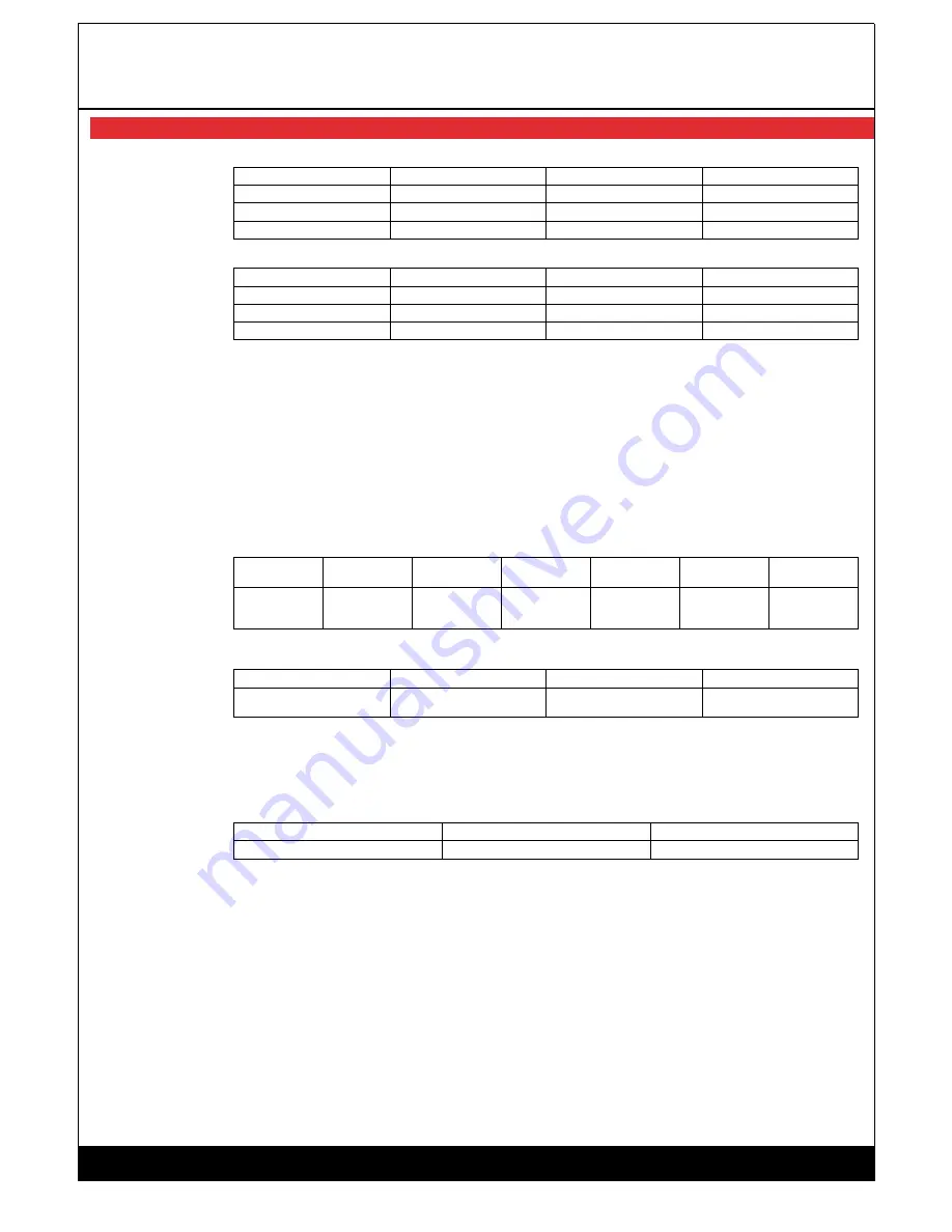
COVERAGE RATES
Conventional Build (Spray, Brush or Roller)
Dry Mils (Microns)
Wet Mils (Microns)
Sq Ft/Gal (m²/Gal)
Suggested
2.5 (65)
3.5 (90)
456 (42.3)
Minimum
2.0 (50)
3.0 (75)
570 (52.2)
Maximum
3.0 (75)
4.5 (115)
380 (35.3)
High-Build (Spray Only)
Dry Mils (Microns)
Wet Mils (Microns)
Sq Ft/Gal (m²/Gal)
Suggested
4.0 (100)
6.0 (150)
285 (26.4)
Minimum
3.0 (75)
4.5 (115)
380 (35.3)
Maximum
5.0 (125)
7.5 (190)
228 (21.2)
Note: Can be spray applied at 3.0 to 5.0 mils (75 to 125 microns) DFT per coat when extra protection or the elimination
of a coat is desired. Allow for overspray and surface irregularities. Film thickness is rounded to the nearest 0.5 mil or 5
microns. Application of coating below minimum or above maximum recommended dry film thicknesses may adversely
affect coating performance. †
MIXING
Stir contents of the container marked Part A, making sure no pigment remains on the bottom. Add the contents of the can
marked Part B to Part A while under agitation. Continue agitation until the two components are thoroughly mixed. When
used with 44-710 Urethane Accelerator, first blend 44-710 into Part A under agitation; continue as above. Do not use
mixed material beyond pot life limits. Caution: Part B is moisture-sensitive and will react with atmospheric moisture.
Unused material must be kept tightly closed at all times.
THINNING
For air or airless spray, thin 15% to 18% or 1 1/4 to 1 1/2 pints (570 to 680 mL) per gallon with No. 24 Thinner. For brush
or roller thin 20% or 1 1/2 pints (760 mL) per gallon with No. 39 Thinner. For air or airless spray at temperatures above
90°F (32°C), thin up to 16% or 1 1/4 pints (600 mL) per gallon with No. 48 Thinner. Note: Thinning is required for proper
application. Caution: Do not add thinner if more than 30 minutes have elapsed after mixing.
POT LIFE
2 hours at 77°F (25°C) unthinned 3 hours at 77°F (25°C) thinned
1 hour at 100°F (38°C) unthinned 2 hours at 100°F (38°C) thinned
APPLICATION EQUIPMENT
Air Spray
Gun
Fluid Tip
Air Cap
Air Hose ID
Mat'l Hose ID
Atomizing
Pressure
Pot Pressure
DeVilbiss JGA
E
704 or 765
5/16" or 3/8"
(7.9 or 9.5 mm)
3/8" or 1/2"
(9.5 or 12.7
mm)
80-90 psi
(5.5-6.2 bar)
20-30 psi
(1.4-2.0 bar)
Low temperatures or longer hoses require higher pot pressure
Airless Spray
Tip Orifice
Atomizing Pressure
Matl'l Hose ID
Manifold Filter
0.013”-0.015”
(330-381 microns)
3500-4000 psi
(241-276 bar)
1/4" or 3/8"
(6.4 or 9.5 mm)
100 mesh
(150 microns)
Use appropriate tip/atomizing pressure for equipment, applicator technique and weather conditions.
Roller: Use 1/4” (6.4 mm) synthetic nap cover. Do not use medium or long nap roller covers. Two coats are required to
obtain dry film thickness above 3.0 mils (75 microns).
Brush: Recommended for small areas only. Use high quality natural or synthetic bristle brushes.
Note: Two coats are required to obtain recommended film thickness.
SURFACE TEMPERATURE
Minimum 40°F (4°C) Maximum 120°F (49°C)
The surface should be dry and at least 5°F (3°C) above the dew point.
Cure time necessary to resist direct contact with moisture at surface temperature:
40°F (4°C): 24 to 32 hours
50°F (10°C): 18 to 24 hours
60°F (16°C): 10 to 16 hours
70°F (21°C): 4 to 8 hours
90°F (32°C): 2 to 4 hours
100°F (38°C): 1 to 2 hours
If the coating is exposed to moisture before the preceding cure parameters are met, dull, flat or spotty-appearing areas
may develop. Actual time will vary with air movement, film thickness and humidity.
CLEANUP
Flush and clean all equipment immediately after use with the recommended thinner or MEK.
† Values may vary with color.
© 9/8/2009, by Tnemec Co., Inc.
PRODUCT DATA SHEET
ENDURA-SHIELD
®
| SERIES 175
WARRANTY & LIMITATION OF SELLER'S LIABILITY: Tnemec Company, Inc. warrants only that its coatings represented herein meet the formulation standards of Tnemec Company, Inc. THE
WARRANTY DESCRIBED IN THE ABOVE PARAGRAPH SHALL BE IN LIEU OF ANY OTHER WARRANTY, EXPRESSED OR IMPLIED, INCLUDING BUT NOT LIMITED TO, ANY IMPLIED
WARRANTY OF MERCHANTABILITY OR FITNESS FOR A PARTICULAR PURPOSE. THERE ARE NO WARRANTIES THAT EXTEND BEYOND THE DESCRIPTION ON THE FACE HEREOF. The
buyer's sole and exclusive remedy against Tnemec Company, Inc. shall be for replacement of the product in the event a defective condition of the product should be found to exist and the
exclusive remedy shall not have failed its essential purpose as long as Tnemec is willing to provide comparable replacement product to the buyer. NO OTHER REMEDY (INCLUDING, BUT NOT
LIMITED TO, INCIDENTAL OR CONSEQUENTIAL DAMAGES FOR LOST PROFITS, LOST SALES, INJURY TO PERSON OR PROPERTY, ENVIRONMENTAL INJURIES OR ANY OTHER INCIDENTAL
OR CONSEQUENTIAL LOSS) SHALL BE AVAILABLE TO THE BUYER. Technical and application information herein is provided for the purpose of establishing a general profile of the coating and
proper coating application procedures. Test performance results were obtained in a controlled environment and Tnemec Company makes no claim that these tests or any other tests, accurately
represent all environments. As application, environmental and design factors can vary significantly, due care should be exercised in the selection and use of the coating.
Tnemec Company Incorporated
6800 Corporate Drive Kansas City, Missouri 64120-1372 1-800-TNEMEC1 Fax: 1-816-483-3969 www.tnemec.com
PDS175 Page 2 of 2
Summary of Contents for VG3B3-B
Page 14: ...GENERAL INFORMATION...
Page 17: ...EQUIPMENT SAFETY DOCUMENTS and PRECAUTIONS...
Page 30: ...U L MOTOR REQUIREMENTS...
Page 31: ......
Page 35: ...PROTECTIVE COATINGS...
Page 37: ...PAINT TECHNICAL DATA SHEETS...
Page 43: ...PASSIVATION DOCUMENTS...
Page 47: ...STORAGE PROCEDURES...
Page 51: ...INSTRUMENTATION...
Page 56: ...VALVES...
Page 58: ...PUMPS...
Page 61: ...MATERIAL SAFETY DATA SHEETS...
Page 65: ......
Page 66: ...PAINT COATING MSDS...
Page 73: ...ADHESIVE ANCHORS MSDS...
Page 74: ...SIMPSON...
Page 95: ......
Page 96: ......
Page 97: ......
Page 98: ......
Page 99: ......
Page 100: ...INSTALLATION AND START UP...
Page 103: ...START UP PAPERS...
Page 125: ...PROCESS AND CONTROL...
Page 181: ...MECHANICAL AND FIELD INSTRUMENT COMPONENT INFORMATION...
Page 182: ...ACTUATOR...
Page 183: ...CORD SET...
Page 185: ...AUMA...
Page 186: ...115V 1ph 60Hz...
Page 190: ...ANCHORS...
Page 191: ...ADHESIVE ANCHOR See Drawing Section 7 for Details...
Page 192: ...MANUAL GUN...
Page 194: ...REFILL PACK...
Page 197: ...MIXING NOZZLE...
Page 199: ...INSTRUMENTATION...
Page 200: ...CONTROLLER...
Page 201: ...THERMO FISHER...
Page 203: ...pH PROBE...
Page 206: ...FLOW METER...
Page 211: ...PRESSURE TRANSMITTER...
Page 213: ...PUMP...
Page 214: ...MEMBRANE FEED PUMP...
Page 217: ...Pump Part 2616713 Gorman Rupp VG3B3 B Centrifugal 2013 12 09 2616713 Pump doc 3 of 3...
Page 220: ...BACKWASH PUMP...
Page 223: ...Pump Part 2616695 Gorman Rupp VG3C3 B Centrifugal 2013 12 09 2616695 Pump doc 3 of 3...
Page 227: ...BUTTERFLY VALVE...
Page 228: ...MANUAL LEVER BUTTERFLY VALVE...
Page 238: ...ELECTRIC BUTTERFLY VALVE...
Page 241: ...SWING CHECK VALVE...
Page 243: ...SOLENOID VALVE...
Page 245: ...MEMBRANE MODULE ACCESSORIES...
Page 254: ...AIR COMPRESSOR ACCESSORIES...
Page 258: ...ELECTRICAL CONTROL PANEL COMPONENT INFORMATION...
Page 265: ...CABLE CONDUIT WIRE...
Page 271: ...CIRCUIT BREAKER...
Page 281: ...COMPUTER and MONITOR...
Page 289: ...ENCLOSURE...
Page 296: ...ENCLOSURE ACCESSORIES...
Page 307: ...ENVIRONMENTAL CONTROL ENCLOSURE...
Page 314: ...FUSE...
Page 329: ...FUSE BLOCK...
Page 336: ...HMI HUMAN MACHINE INTERFACE...
Page 343: ...MAIN DISCONNECT...
Page 350: ...MAIN DISCONNECT ACCESSORIES...
Page 354: ...MOTOR CONTROL...
Page 368: ...NETWORK...
Page 379: ...PILOT DEVICE...
Page 392: ...PLC PROGRAMMABLE LOGIC CONTROL...
Page 420: ...PRINTERS...
Page 424: ...POWER SUPPLY...
Page 426: ...Power Supply Part 2751312 Allen Bradley 2008 02 28 2751312 AB Power Supply doc 2 of 5...
Page 427: ...Power Supply Part 2751312 Allen Bradley 2008 02 28 2751312 AB Power Supply doc 3 of 5...
Page 428: ...Power Supply Part 2751312 Allen Bradley 2008 02 28 2751312 AB Power Supply doc 4 of 5...
Page 429: ...Power Supply Part 2751312 Allen Bradley 2008 02 28 2751312 AB Power Supply doc 5 of 5...
Page 434: ...RELAY CONTROL...
Page 440: ...SURGE SUPPRESSOR TRANSIENT FILTER...
Page 447: ...TERMINAL BLOCK ACCESSORIES...
Page 471: ...TIMERS...
Page 477: ...TRANSFORMER ACCESSORIES...
Page 482: ...UPS UNINTERRUPTIBLE POWER SUPPLY...
Page 489: ...MAINTENANCE AND TROUBLESHOOTING...
Page 498: ...COMPONENT PRODUCTS EQUIPMENT O M INSTRUCTION MANUALS...
Page 499: ...ACTUATOR...
Page 500: ...ELECTRIC...
Page 534: ...ADHESIVE ANCHOR O M...
Page 535: ......
Page 537: ...INSTRUMENTATION O M...
Page 538: ...FLOW METER...
Page 684: ...5 NOTES 30 IFC 100 www krohne com 07 2010 4000124104 QS IFC 100 R04 en...
Page 685: ...NOTES 5 31 IFC 100 www krohne com 07 2010 4000124104 QS IFC 100 R04 en...
Page 687: ......
Page 688: ......
Page 689: ......
Page 690: ......
Page 691: ......
Page 692: ......
Page 693: ......
Page 694: ......
Page 695: ......
Page 696: ......
Page 697: ......
Page 698: ......
Page 699: ......
Page 700: ......
Page 701: ......
Page 702: ......
Page 703: ......
Page 704: ......
Page 705: ......
Page 706: ......
Page 707: ......
Page 708: ......
Page 709: ......
Page 710: ......
Page 711: ......
Page 712: ......
Page 713: ......
Page 714: ......
Page 715: ......
Page 716: ......
Page 717: ......
Page 718: ......
Page 719: ......
Page 720: ......
Page 721: ......
Page 722: ......
Page 723: ...TURBIDITY MONITORING O M...
Page 734: ...10 Installation Figure 4 1720E Dimensions...
Page 738: ...14 System Startup...
Page 746: ...22 Operation...
Page 754: ...30 Troubleshooting...
Page 760: ...36 Modbus Register Information...
Page 762: ...38 Index...
Page 763: ...DOC023 53 80221 FT660 sc 01 2012 Edition 2 User Manual...
Page 764: ......
Page 782: ...1 2 18 English...
Page 783: ...3 4 English 19...
Page 790: ...26 English...
Page 791: ......
Page 793: ...CONTROLLER...
Page 794: ...Thermo Scientific AquaSensors AV38 Local Display and Controller User Guide...
Page 873: ......
Page 875: ...pH PROBE...
Page 880: ...PRESSURE TRANSMITTER...
Page 881: ......
Page 900: ...A 9 Keller America Inc User s Guide Rev 10 11...
Page 901: ...A 10 Keller America Inc User s Guide Rev 10 11...
Page 904: ...MEMBRANE MODULE...
Page 905: ...inge GmbH Installation Operation and Maintenance Guidelines inge T Rack vario...
Page 934: ......
Page 935: ...Appendix B Process Specification inge UF...
Page 957: ...PUMPS...
Page 958: ...GORMAN RUPP PUMP...
Page 959: ......
Page 960: ......
Page 961: ......
Page 962: ......
Page 963: ......
Page 964: ......
Page 965: ......
Page 966: ......
Page 967: ......
Page 968: ......
Page 969: ......
Page 970: ......
Page 971: ......
Page 972: ......
Page 973: ......
Page 974: ......
Page 975: ......
Page 976: ......
Page 977: ......
Page 978: ......
Page 979: ......
Page 980: ......
Page 981: ......
Page 982: ......
Page 983: ......
Page 984: ......
Page 985: ......
Page 986: ......
Page 987: ......
Page 988: ......
Page 989: ......
Page 990: ......
Page 991: ......
Page 1056: ...VALVES...
Page 1057: ...NIBCO VALVE...
Page 1058: ...WAFER BUTTERFLY VALVE...
Page 1068: ...MILLIKEN VALVE...
Page 1069: ...MILLIKEN BUTTERFLY VALVE...
Page 1070: ......
Page 1077: ...MECHANICAL DRAWINGS...
Page 1110: ...ELECTRICAL DRAWINGS...
Page 1119: ......
Page 1153: ......
Page 1157: ......


