


3
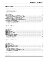
Section 1
Specifications
Specifications are subject to change without notice.
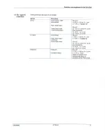
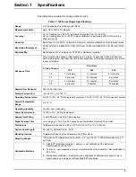
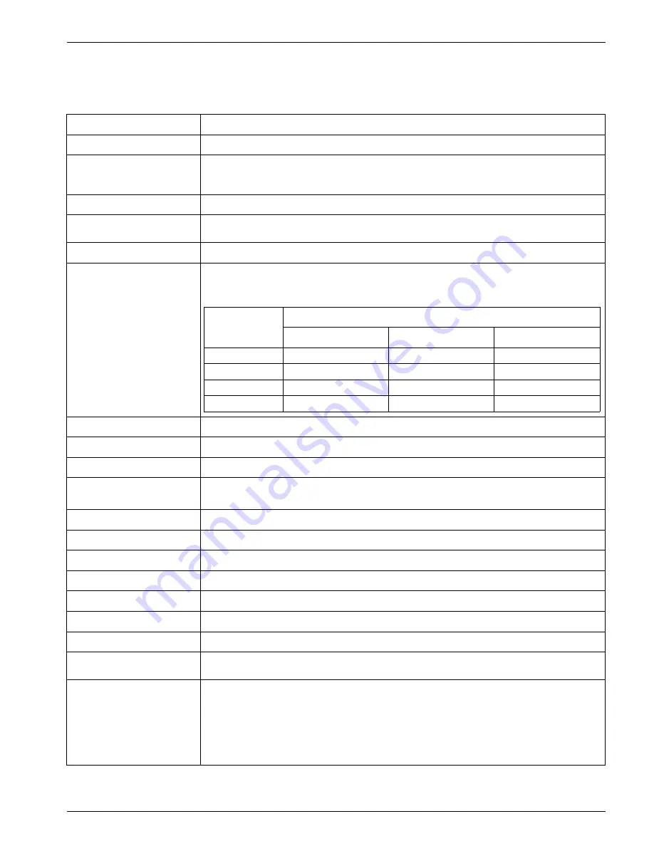
Table 1 1720E Low Range Specifications
Range
0–100 nephelometric turbidity units (NTU)
Measurement Units
mg/L, NTU, TE/F, FTU, Degree
Accuracy
1
± 2% of reading or ± 0.02 NTU (whichever is greater) from 0 to 40 NTU;
± 5% of reading from 40 to 100 NTU (when calibration is performed at 20.0 NTU with the
offset turned off).
Linearity
1
Better than 1% 0–40 NTU on formazin. Allows for accurate calibration at high turbidity values.
Resolution (Displayed)
0.0001 NTU
up to 9.9999 NTU; 0.001 NTU from 10.000 to 99.999 NTU; 0.01 NTU at 100.00
NTU
Repeatability
Better than ±1.0% of reading or ±0.002 NTU, whichever is greater
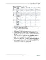
Response Time
For a full-scale step change, initial response in 1 minute, 15 seconds. Varies with flow rate,
see the table below. The response time is also dependent on the signal averaging time, which
is user selectable.
Sample Flow Required
250 to 750 mL/minute
Storage Temperature
–20 to 60 °C (–4 to 140 °F)
Operating Temperature
0 to 50 °C (32–122 °F) for single sensor system, 0 to 40 °C (32–104 °F) for two sensor system
Sample Temperature
Range
0 to 70 °C
Operating Humidity
5 to 95% non-condensing
Power Requirements
12 VDC ± 5%, 12.5 Watts maximum
Sample Inlet Fitting
1
/
8
barb fitting to ¼-inch NPT male adapter
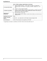
Signal Average Time
no averaging, 6, 30, 60, and 90 seconds, user selectable. Default is 30 seconds.
Dimensions
Turbidimeter body and cap: 25.4 x 30.5 x 40.6 cm (10 x 12 x 16 inches)
Sensor Cable Length
2 m (6.6 ft); Optional 7.62 m (25 ft)
Mounting Options
Turbidimeter Body and Head Assembly: Wall; floor stand
Shipping Weight
1720E Series 2 Turbidimeter and Controller: 6.31 kg (13.5 lb); 1720E Turbidimeter only: 4.71
kg (10 lb)
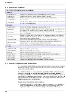
Calibration Methods
1.
StablCal
®
(stabilized formazin) – primary or wet calibration of the instrument.
Recommended at 20.0 NTU.
2.
Formazin – user-prepared primary or wet calibration of the instrument. Recommended at
20.0 NTU.
3.
Multi-sensor calibration – Performed with a specialized calibration procedure for up to
eight sensors on a single set of fresh StablCal
®
standards.
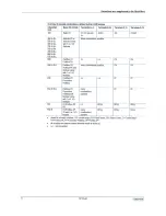
% Step Change
Flow Rate
750
500
250
10
1¼ minutes
1½ minutes
2½ minutes
50
2 minutes
2½ minutes
6 minutes
90
3½ minutes
3½ minutes
9 minutes
99
4 minutes
5 minutes
12 minutes
Summary of Contents for VG3B3-B
Page 14: ...GENERAL INFORMATION...
Page 17: ...EQUIPMENT SAFETY DOCUMENTS and PRECAUTIONS...
Page 30: ...U L MOTOR REQUIREMENTS...
Page 31: ......
Page 35: ...PROTECTIVE COATINGS...
Page 37: ...PAINT TECHNICAL DATA SHEETS...
Page 43: ...PASSIVATION DOCUMENTS...
Page 47: ...STORAGE PROCEDURES...
Page 51: ...INSTRUMENTATION...
Page 56: ...VALVES...
Page 58: ...PUMPS...
Page 61: ...MATERIAL SAFETY DATA SHEETS...
Page 65: ......
Page 66: ...PAINT COATING MSDS...
Page 73: ...ADHESIVE ANCHORS MSDS...
Page 74: ...SIMPSON...
Page 95: ......
Page 96: ......
Page 97: ......
Page 98: ......
Page 99: ......
Page 100: ...INSTALLATION AND START UP...
Page 103: ...START UP PAPERS...
Page 125: ...PROCESS AND CONTROL...
Page 181: ...MECHANICAL AND FIELD INSTRUMENT COMPONENT INFORMATION...
Page 182: ...ACTUATOR...
Page 183: ...CORD SET...
Page 185: ...AUMA...
Page 186: ...115V 1ph 60Hz...
Page 190: ...ANCHORS...
Page 191: ...ADHESIVE ANCHOR See Drawing Section 7 for Details...
Page 192: ...MANUAL GUN...
Page 194: ...REFILL PACK...
Page 197: ...MIXING NOZZLE...
Page 199: ...INSTRUMENTATION...
Page 200: ...CONTROLLER...
Page 201: ...THERMO FISHER...
Page 203: ...pH PROBE...
Page 206: ...FLOW METER...
Page 211: ...PRESSURE TRANSMITTER...
Page 213: ...PUMP...
Page 214: ...MEMBRANE FEED PUMP...
Page 217: ...Pump Part 2616713 Gorman Rupp VG3B3 B Centrifugal 2013 12 09 2616713 Pump doc 3 of 3...
Page 220: ...BACKWASH PUMP...
Page 223: ...Pump Part 2616695 Gorman Rupp VG3C3 B Centrifugal 2013 12 09 2616695 Pump doc 3 of 3...
Page 227: ...BUTTERFLY VALVE...
Page 228: ...MANUAL LEVER BUTTERFLY VALVE...
Page 238: ...ELECTRIC BUTTERFLY VALVE...
Page 241: ...SWING CHECK VALVE...
Page 243: ...SOLENOID VALVE...
Page 245: ...MEMBRANE MODULE ACCESSORIES...
Page 254: ...AIR COMPRESSOR ACCESSORIES...
Page 258: ...ELECTRICAL CONTROL PANEL COMPONENT INFORMATION...
Page 265: ...CABLE CONDUIT WIRE...
Page 271: ...CIRCUIT BREAKER...
Page 281: ...COMPUTER and MONITOR...
Page 289: ...ENCLOSURE...
Page 296: ...ENCLOSURE ACCESSORIES...
Page 307: ...ENVIRONMENTAL CONTROL ENCLOSURE...
Page 314: ...FUSE...
Page 329: ...FUSE BLOCK...
Page 336: ...HMI HUMAN MACHINE INTERFACE...
Page 343: ...MAIN DISCONNECT...
Page 350: ...MAIN DISCONNECT ACCESSORIES...
Page 354: ...MOTOR CONTROL...
Page 368: ...NETWORK...
Page 379: ...PILOT DEVICE...
Page 392: ...PLC PROGRAMMABLE LOGIC CONTROL...
Page 420: ...PRINTERS...
Page 424: ...POWER SUPPLY...
Page 426: ...Power Supply Part 2751312 Allen Bradley 2008 02 28 2751312 AB Power Supply doc 2 of 5...
Page 427: ...Power Supply Part 2751312 Allen Bradley 2008 02 28 2751312 AB Power Supply doc 3 of 5...
Page 428: ...Power Supply Part 2751312 Allen Bradley 2008 02 28 2751312 AB Power Supply doc 4 of 5...
Page 429: ...Power Supply Part 2751312 Allen Bradley 2008 02 28 2751312 AB Power Supply doc 5 of 5...
Page 434: ...RELAY CONTROL...
Page 440: ...SURGE SUPPRESSOR TRANSIENT FILTER...
Page 447: ...TERMINAL BLOCK ACCESSORIES...
Page 471: ...TIMERS...
Page 477: ...TRANSFORMER ACCESSORIES...
Page 482: ...UPS UNINTERRUPTIBLE POWER SUPPLY...
Page 489: ...MAINTENANCE AND TROUBLESHOOTING...
Page 498: ...COMPONENT PRODUCTS EQUIPMENT O M INSTRUCTION MANUALS...
Page 499: ...ACTUATOR...
Page 500: ...ELECTRIC...
Page 534: ...ADHESIVE ANCHOR O M...
Page 535: ......
Page 537: ...INSTRUMENTATION O M...
Page 538: ...FLOW METER...
Page 684: ...5 NOTES 30 IFC 100 www krohne com 07 2010 4000124104 QS IFC 100 R04 en...
Page 685: ...NOTES 5 31 IFC 100 www krohne com 07 2010 4000124104 QS IFC 100 R04 en...
Page 687: ......
Page 688: ......
Page 689: ......
Page 690: ......
Page 691: ......
Page 692: ......
Page 693: ......
Page 694: ......
Page 695: ......
Page 696: ......
Page 697: ......
Page 698: ......
Page 699: ......
Page 700: ......
Page 701: ......
Page 702: ......
Page 703: ......
Page 704: ......
Page 705: ......
Page 706: ......
Page 707: ......
Page 708: ......
Page 709: ......
Page 710: ......
Page 711: ......
Page 712: ......
Page 713: ......
Page 714: ......
Page 715: ......
Page 716: ......
Page 717: ......
Page 718: ......
Page 719: ......
Page 720: ......
Page 721: ......
Page 722: ......
Page 723: ...TURBIDITY MONITORING O M...
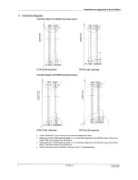
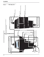
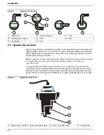
Page 734: ...10 Installation Figure 4 1720E Dimensions...
Page 738: ...14 System Startup...
Page 746: ...22 Operation...
Page 754: ...30 Troubleshooting...
Page 760: ...36 Modbus Register Information...
Page 762: ...38 Index...
Page 763: ...DOC023 53 80221 FT660 sc 01 2012 Edition 2 User Manual...
Page 764: ......
Page 782: ...1 2 18 English...
Page 783: ...3 4 English 19...
Page 790: ...26 English...
Page 791: ......
Page 793: ...CONTROLLER...
Page 794: ...Thermo Scientific AquaSensors AV38 Local Display and Controller User Guide...
Page 873: ......
Page 875: ...pH PROBE...
Page 880: ...PRESSURE TRANSMITTER...
Page 881: ......
Page 900: ...A 9 Keller America Inc User s Guide Rev 10 11...
Page 901: ...A 10 Keller America Inc User s Guide Rev 10 11...
Page 904: ...MEMBRANE MODULE...
Page 905: ...inge GmbH Installation Operation and Maintenance Guidelines inge T Rack vario...
Page 934: ......
Page 935: ...Appendix B Process Specification inge UF...
Page 957: ...PUMPS...
Page 958: ...GORMAN RUPP PUMP...
Page 959: ......
Page 960: ......
Page 961: ......
Page 962: ......
Page 963: ......
Page 964: ......
Page 965: ......
Page 966: ......
Page 967: ......
Page 968: ......
Page 969: ......
Page 970: ......
Page 971: ......
Page 972: ......
Page 973: ......
Page 974: ......
Page 975: ......
Page 976: ......
Page 977: ......
Page 978: ......
Page 979: ......
Page 980: ......
Page 981: ......
Page 982: ......
Page 983: ......
Page 984: ......
Page 985: ......
Page 986: ......
Page 987: ......
Page 988: ......
Page 989: ......
Page 990: ......
Page 991: ......
Page 1056: ...VALVES...
Page 1057: ...NIBCO VALVE...
Page 1058: ...WAFER BUTTERFLY VALVE...
Page 1068: ...MILLIKEN VALVE...
Page 1069: ...MILLIKEN BUTTERFLY VALVE...
Page 1070: ......
Page 1077: ...MECHANICAL DRAWINGS...
Page 1110: ...ELECTRICAL DRAWINGS...
Page 1119: ......
Page 1153: ......
Page 1157: ......


