Thermo Scientific AquaSensors
™
AV38 Local Display and Controller User Guide
21
3.
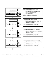
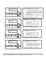
MENU STRUCTURE AND NAVIGATION
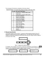
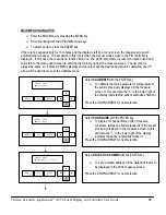
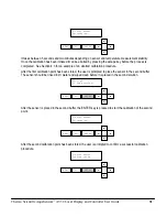
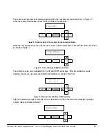
The Main Menu is accessed by pressing the MENU key when the AV38 is in Analyzer Mode (measure screen).
The menu structure is navigated using ENTER, UP/DOWN arrows, and ESC keys.
¾
Use the UP/DOWN arrow keys to scroll through the list of Menu options.
¾
Use the ENTER key to select an option.
¾
Use the ESC key to move up in the structure.
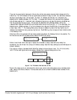
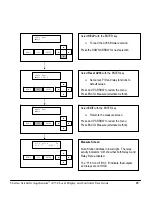
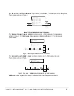
The end of the list of menu options is always the EXIT function. Pressing ENTER on the EXIT screen will bring
up the MEASURE screen.
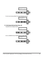
The (
≡
) symbol is used to indicate that the user is in the menu structure. At the leaf of each branch of the menu
structure, the user is able to enter a value or make a choice. The value to be entered or the choice to be made
will be surrounded by parentheses (
(
)
). The name of the value being entered or choice being made will appear
on the upper line of the screen and be appended with a question mark (
?
) to indicate that the user is to provide
input.
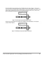
The RIGHT arrow symbol (
>
) on the screen indicates that downward navigation through the menu structure is
possible. The LEFT arrow symbol (
<
) on the screen indicates that upward navigation through the menu
structure is possible.
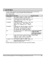
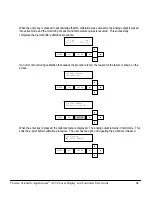
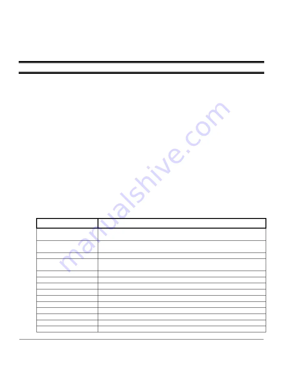
Calibration and configuration of a specific sensor is accessed by pressing the MENU key from the measure
screen for that sensor. Main menu items are listed as follows:
Table 2: Main menu items.
Main Menu Item
Function
Calibrate
(Station Number)
Sensor calibration choices are automatically available for installed sensor head.
Enter the MENU from the measure display of interest – station in lower right.
Configure
(Station Number)
Configuration choices are automatically available for the installed sensor head.
Enter the MENU from the measure display of interest – station in lower right.
DataStick Comms
Set the station address, baud rate and parity for the Modbus DataStick of interest.
Chlorine Configure
Select free chlorine or HOCL
concentration for output. Select pH compensation – fixed
or active. (Only when Chlorine DataStick Present).
Hold Outputs
Holds the 4-20 mA and Relay outputs
Analog Output 1
Set 4 mA and 20 mA values. Calibrate and test the analog output with a milliammeter.
Analog Output 2 (option)
Set 4 mA and 20 mA values. Calibrate and test the current output with a milliammeter.
PID Controller
Set up PID control functions for analog outputs. Available with pH or Conductivity.
Relay A (option)
Set timer, alarm, or control functions. (Optional)
Relay B (option)
Set timer, alarm, or control functions. (Optional)
Diagnose (pH DataStick only) Indicates the pH Sensor Head slope
Help
Indicates AV38 firmware version
Reset AV38
Resets AV38 configuration to default analog output, relay and PID settings.
Exit
Returns to the measure screen
Summary of Contents for VG3B3-B
Page 14: ...GENERAL INFORMATION...
Page 17: ...EQUIPMENT SAFETY DOCUMENTS and PRECAUTIONS...
Page 30: ...U L MOTOR REQUIREMENTS...
Page 31: ......
Page 35: ...PROTECTIVE COATINGS...
Page 37: ...PAINT TECHNICAL DATA SHEETS...
Page 43: ...PASSIVATION DOCUMENTS...
Page 47: ...STORAGE PROCEDURES...
Page 51: ...INSTRUMENTATION...
Page 56: ...VALVES...
Page 58: ...PUMPS...
Page 61: ...MATERIAL SAFETY DATA SHEETS...
Page 65: ......
Page 66: ...PAINT COATING MSDS...
Page 73: ...ADHESIVE ANCHORS MSDS...
Page 74: ...SIMPSON...
Page 95: ......
Page 96: ......
Page 97: ......
Page 98: ......
Page 99: ......
Page 100: ...INSTALLATION AND START UP...
Page 103: ...START UP PAPERS...
Page 125: ...PROCESS AND CONTROL...
Page 181: ...MECHANICAL AND FIELD INSTRUMENT COMPONENT INFORMATION...
Page 182: ...ACTUATOR...
Page 183: ...CORD SET...
Page 185: ...AUMA...
Page 186: ...115V 1ph 60Hz...
Page 190: ...ANCHORS...
Page 191: ...ADHESIVE ANCHOR See Drawing Section 7 for Details...
Page 192: ...MANUAL GUN...
Page 194: ...REFILL PACK...
Page 197: ...MIXING NOZZLE...
Page 199: ...INSTRUMENTATION...
Page 200: ...CONTROLLER...
Page 201: ...THERMO FISHER...
Page 203: ...pH PROBE...
Page 206: ...FLOW METER...
Page 211: ...PRESSURE TRANSMITTER...
Page 213: ...PUMP...
Page 214: ...MEMBRANE FEED PUMP...
Page 217: ...Pump Part 2616713 Gorman Rupp VG3B3 B Centrifugal 2013 12 09 2616713 Pump doc 3 of 3...
Page 220: ...BACKWASH PUMP...
Page 223: ...Pump Part 2616695 Gorman Rupp VG3C3 B Centrifugal 2013 12 09 2616695 Pump doc 3 of 3...
Page 227: ...BUTTERFLY VALVE...
Page 228: ...MANUAL LEVER BUTTERFLY VALVE...
Page 238: ...ELECTRIC BUTTERFLY VALVE...
Page 241: ...SWING CHECK VALVE...
Page 243: ...SOLENOID VALVE...
Page 245: ...MEMBRANE MODULE ACCESSORIES...
Page 254: ...AIR COMPRESSOR ACCESSORIES...
Page 258: ...ELECTRICAL CONTROL PANEL COMPONENT INFORMATION...
Page 265: ...CABLE CONDUIT WIRE...
Page 271: ...CIRCUIT BREAKER...
Page 281: ...COMPUTER and MONITOR...
Page 289: ...ENCLOSURE...
Page 296: ...ENCLOSURE ACCESSORIES...
Page 307: ...ENVIRONMENTAL CONTROL ENCLOSURE...
Page 314: ...FUSE...
Page 329: ...FUSE BLOCK...
Page 336: ...HMI HUMAN MACHINE INTERFACE...
Page 343: ...MAIN DISCONNECT...
Page 350: ...MAIN DISCONNECT ACCESSORIES...
Page 354: ...MOTOR CONTROL...
Page 368: ...NETWORK...
Page 379: ...PILOT DEVICE...
Page 392: ...PLC PROGRAMMABLE LOGIC CONTROL...
Page 420: ...PRINTERS...
Page 424: ...POWER SUPPLY...
Page 426: ...Power Supply Part 2751312 Allen Bradley 2008 02 28 2751312 AB Power Supply doc 2 of 5...
Page 427: ...Power Supply Part 2751312 Allen Bradley 2008 02 28 2751312 AB Power Supply doc 3 of 5...
Page 428: ...Power Supply Part 2751312 Allen Bradley 2008 02 28 2751312 AB Power Supply doc 4 of 5...
Page 429: ...Power Supply Part 2751312 Allen Bradley 2008 02 28 2751312 AB Power Supply doc 5 of 5...
Page 434: ...RELAY CONTROL...
Page 440: ...SURGE SUPPRESSOR TRANSIENT FILTER...
Page 447: ...TERMINAL BLOCK ACCESSORIES...
Page 471: ...TIMERS...
Page 477: ...TRANSFORMER ACCESSORIES...
Page 482: ...UPS UNINTERRUPTIBLE POWER SUPPLY...
Page 489: ...MAINTENANCE AND TROUBLESHOOTING...
Page 498: ...COMPONENT PRODUCTS EQUIPMENT O M INSTRUCTION MANUALS...
Page 499: ...ACTUATOR...
Page 500: ...ELECTRIC...
Page 534: ...ADHESIVE ANCHOR O M...
Page 535: ......
Page 537: ...INSTRUMENTATION O M...
Page 538: ...FLOW METER...
Page 684: ...5 NOTES 30 IFC 100 www krohne com 07 2010 4000124104 QS IFC 100 R04 en...
Page 685: ...NOTES 5 31 IFC 100 www krohne com 07 2010 4000124104 QS IFC 100 R04 en...
Page 687: ......
Page 688: ......
Page 689: ......
Page 690: ......
Page 691: ......
Page 692: ......
Page 693: ......
Page 694: ......
Page 695: ......
Page 696: ......
Page 697: ......
Page 698: ......
Page 699: ......
Page 700: ......
Page 701: ......
Page 702: ......
Page 703: ......
Page 704: ......
Page 705: ......
Page 706: ......
Page 707: ......
Page 708: ......
Page 709: ......
Page 710: ......
Page 711: ......
Page 712: ......
Page 713: ......
Page 714: ......
Page 715: ......
Page 716: ......
Page 717: ......
Page 718: ......
Page 719: ......
Page 720: ......
Page 721: ......
Page 722: ......
Page 723: ...TURBIDITY MONITORING O M...
Page 734: ...10 Installation Figure 4 1720E Dimensions...
Page 738: ...14 System Startup...
Page 746: ...22 Operation...
Page 754: ...30 Troubleshooting...
Page 760: ...36 Modbus Register Information...
Page 762: ...38 Index...
Page 763: ...DOC023 53 80221 FT660 sc 01 2012 Edition 2 User Manual...
Page 764: ......
Page 782: ...1 2 18 English...
Page 783: ...3 4 English 19...
Page 790: ...26 English...
Page 791: ......
Page 793: ...CONTROLLER...
Page 794: ...Thermo Scientific AquaSensors AV38 Local Display and Controller User Guide...
Page 873: ......
Page 875: ...pH PROBE...
Page 880: ...PRESSURE TRANSMITTER...
Page 881: ......
Page 900: ...A 9 Keller America Inc User s Guide Rev 10 11...
Page 901: ...A 10 Keller America Inc User s Guide Rev 10 11...
Page 904: ...MEMBRANE MODULE...
Page 905: ...inge GmbH Installation Operation and Maintenance Guidelines inge T Rack vario...
Page 934: ......
Page 935: ...Appendix B Process Specification inge UF...
Page 957: ...PUMPS...
Page 958: ...GORMAN RUPP PUMP...
Page 959: ......
Page 960: ......
Page 961: ......
Page 962: ......
Page 963: ......
Page 964: ......
Page 965: ......
Page 966: ......
Page 967: ......
Page 968: ......
Page 969: ......
Page 970: ......
Page 971: ......
Page 972: ......
Page 973: ......
Page 974: ......
Page 975: ......
Page 976: ......
Page 977: ......
Page 978: ......
Page 979: ......
Page 980: ......
Page 981: ......
Page 982: ......
Page 983: ......
Page 984: ......
Page 985: ......
Page 986: ......
Page 987: ......
Page 988: ......
Page 989: ......
Page 990: ......
Page 991: ......
Page 1056: ...VALVES...
Page 1057: ...NIBCO VALVE...
Page 1058: ...WAFER BUTTERFLY VALVE...
Page 1068: ...MILLIKEN VALVE...
Page 1069: ...MILLIKEN BUTTERFLY VALVE...
Page 1070: ......
Page 1077: ...MECHANICAL DRAWINGS...
Page 1110: ...ELECTRICAL DRAWINGS...
Page 1119: ......
Page 1153: ......
Page 1157: ......


