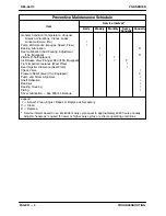
background image

VGH SERIES

OM-06114

MAINTENANCE & REPAIR

PAGE E - 6

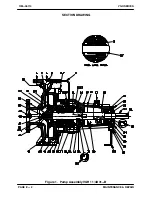
outboard bearing (19) from the shaft. Remove the
inboard bearing spacer (21).

After removing the shaft and bearings, clean and
inspect the bearings as follows.

It is 

strongly

 recommended that the bear­

ings be replaced 

any

 time the shaft and

bearings are removed.

Clean the bearing housing, shaft and all compo­
nent parts (except the bearings) with a soft cloth
soaked in cleaning solvent. Inspect the parts for
wear or damage and replace as necessary.

Most cleaning solvents are toxic and
flammable. Use them only in a well ven­
tilated area free from excessive heat,
sparks, and flame. Read and follow all
precautions printed on solvent contain­
ers.

Clean the bearings


thoroughly in 

fresh

 cleaning

solvent. Dry the bearings with filtered compressed
air and coat with light oil.

Bearings must be kept free of all dirt and
foreign material. failure to do so will greatly
shorten bearing life. 

Do not

 spin dry bear­

ings. This may scratch the balls or races
and cause premature bearing failure.

Rotate the bearings by hand to check for rough­
ness or binding and inspect the bearing rollers and
balls. If rotation is rough or the bearing rollers or
balls are discolored, replace the bearings.

Replace the bearings, shaft, or bearing housing as
required if the proper bearing fit is not achieved.

Shaft and Bearing Reassembly And Installation

Clean and inspect the bearings as indicated in

Shaft and Bearing Removal and Disassembly

.

It is 

strongly

 recommended that the bear­

ings be replaced 

any

 time the shaft and

and bearings are removed.

The outboard bearing (19) and the inner race of the
inboard bearing (31) may be heated to ease instal­
lation. An induction heater, hot oil bath, electric
oven, or hot plate may be used to heat the bearing.
Bearings should 

never

 be heated with a direct

flame or directly on a hot plate.

NOTE

If a hot oil bath is used to heat the bearing, both the
oil and the container must be 

absolutely

 clean. If

the oil has been previously used, it must be


thor­

oughly

 filtered.

Install the inboard bearing spacer (21).

Heat the outboard bearing and inner race of the in­
borad bearing (31) to a uniform temperature 

no

higher than

 250

_

F (120

_

C), and slide the bearings

it onto the shaft, one at a time, until fully seated.
This should be done quickly, in one continuous
motion, to prevent the bearings from cooling and
sticking on the shaft.

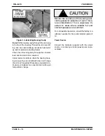
Use caution when handling hot bear­
ings to prevent burns.

After the bearings have been installed and allowed
to cool, check to ensure that they have not moved
out of position in shrinking. If movement has oc­
curred, use a suitably sized sleeve and a press to
reposition the bearings.

When installing the bearings onto the
shaft, 

never

 press or hit against the outer

Summary of Contents for VGH Series

Page 1: ...14 02 April 16 2008 Rev A 09 20 16 GORMAN RUPP PUMPS www grpumps com e2008 Gorman Rupp Pumps Printed in U S A INSTALLATION OPERATION AND MAINTENANCE MANUAL WITH PARTS LIST VGH SERIES PUMP MODEL VGH1 1 4D31 B ...

Page 2: ...erial number and e mail address required RECORD YOUR PUMP MODEL AND SERIAL NUMBER Please record your pump model and serial number in the spaces provided below Your Gorman Rupp distributor needs this information when you require parts or service Pump Model Serial Number ...

Page 3: ...Positioning PAGE B 3 DISCHARGE LINES PAGE B 4 Siphoning PAGE B 4 Valves PAGE B 4 LUBRICATION PAGE B 4 Bearings PAGE B 4 Seal Assembly PAGE B 4 ALIGNMENT PAGE B 4 Coupled Drives PAGE B 5 V Belt Drives PAGE B 5 ELECTRICAL CONNECTIONS PAGE B 6 GROUNDING PAGE B 6 OPERATION SECTION C PAGE C 1 PRIMING PAGE C 1 Hand Primers PAGE C 1 Exhaust Primers PAGE C 2 Auxiliary Ejectors PAGE C 2 Vacuum Pumps PAGE C...

Page 4: ... PAGE E 1 PARTS LIST Pump End Assembly PAGE E 3 PUMP AND SEAL DISASSEMBLY AND REASSEMBLY PAGE E 4 Pump Casing and Impeller Removal PAGE E 4 Wear Ring Removal PAGE E 5 Seal Removal PAGE E 5 Shaft and Bearing Removal And Disassembly PAGE E 5 Shaft and Bearing Reassembly and Installation PAGE E 6 Wear Ring Installation PAGE E 7 Seal Installation PAGE E 7 Impeller and Pump Casing Installation PAGE E 9...

Page 5: ... P O Box 1217 Mansfield Ohio 44901 1217 Phone 419 755 1011 or Gorman Rupp of Canada Limited 70 Burwell Road St Thomas Ontario N5P 3R7 Phone 519 631 2870 For information or technical assistance on the power source contact the power source manufac turer s local dealer or representative HAZARD AND INSTRUCTION DEFINITIONS The following are used to alert maintenance per sonnel to procedures which requi...

Page 6: ...n trained solids Only the Gorman Rupp Company or an authorized Gorman Rupp distributor may modify a pump or approve its use for handling volatile flammable liquids If the pump is used for handling volatile flammable liquids all drivers and or controls must meet in dustry standards and codes for use in an explosive atmosphere Do not at tempt to pump liquids for which the pump driver and or controls...

Page 7: ... couplings or other rotating parts Exposed rotating parts can catch clothing fingers or tools causing severe injury to person nel Do not operate the pump against a closed discharge valve for long periods of time If operated against a closed dis charge valve pump components will deteriorate and the liquid could come to a boil build pressure and cause the pump casing to rupture or explode Overheated...

Page 8: ...y read all tags decals and markings on the pump assembly and perform all duties indicated d Check levels and lubricate as necessary Re fer to LUBRICATION in the MAINTENANCE AND REPAIR section of this manual and per form duties as instructed e If the pump has been stored for more than 12 months some of the components or lubri cants may have exceeded their maximum shelf life These must be inspected ...

Page 9: ... not tapped drill and tap the suction and discharge lines not less than 18 inches 457 2 mm from the suction and discharge ports and install the lines Installation closer to the pump may result in erratic readings SUCTION LINES To avoid air pockets which could affect pump prim ing the suction line must be as short and direct as possible When operation involves a suction lift the line must always sl...

Page 10: ...ed air to escape from the liquid before it is drawn into the suction inlet If two suction lines are installed in a single sump the flow paths may interact reducing the efficiency of one or both pumps To avoid this position the suction inlets so that they are separated by a dis tance equal to at least 3 times the diameter of the suction pipe Suction Line Positioning The depth of submergence of the ...

Page 11: ...e constant level oiler FILL ONLY THROUGH CONSTANT LEVEL OILER DO NOT FILL THROUGH VENT PLUG Figure 2 Lubricating Bearing Cavity Do not fill the bearing cavity through the vent plug in the top of the housing This will result in over fill ing and can cause leakage excessive heat build up and or premature bearing failure Check the oil level regularly through the constant level oiler and add oil as re...

Page 12: ...t all points see Fig ure 3A Figure 3A Aligning Spider Type Couplings Figure 3B Aligning Non Spider Type Couplings Align non spider type couplings by using a feeler gauge or taper gauge between the coupling halves every 90_ The coupling is in alignment when the hubs are the same distance apart at all points see Figure 3B Check parallel adjustment by laying a straightedge across both coupling rims a...

Page 13: ...upplied with the motor for specific instruc tions The electrical power used to operate the pump is high enough to cause injury or death Obtain the services of a qualified electrician to make all electrical con nections If the pump is powered by an electric motor do not operate a non explosion proof motor in an explosive atmo sphere An explosion which may cause severe personal injury or death could...

Page 14: ...ght and that the pump is securely mounted Check that the pump is properly lubri cated see LUBRICATION in the MAINTENANCE AND REPAIR manual This is not a self priming pump so an external priming device must be used if the pump is in stalled on a suction lift A foot valve may be in stalled at the end of the suction pipe to maintain the prime however this may adversely affect pump performance due to ...

Page 15: ...ressed air water or exhaust gases To prime a pump using an ejec tor open the gas cock in the priming line and oper ate the ejector until liquid is thrown out the ejector nozzle Vacuum Pumps Air can be exhausted to prime a pump by using a vacuum pump Either a wet type or a dry type vac uum pump may be used however a wet type is preferred since it will not be damaged if liquid en ters it If a dry va...

Page 16: ...Check If a suction strainer has been shipped with the pump or installed by the user check the strainer regularly and clean it as necessary The strainer should also be checked if pump flow rate begins to drop If a vacuum suction gauge has been in stalled monitor and record the readings regularly to detect strainer blockage Never introduce air or steam pressure into the pump casing or piping to remo...

Page 17: ...he draining process Clean out any remaining solids by flushing with a hose BEARING TEMPERATURE CHECK Bearings normally run at higher than ambient tem peratures because of heat generated by friction Temperatures up to 160_F 71_ C are considered normal for bearings and they can operate safely to at least 180_F 82_ C Checking bearing temperatures by hand is inaccu rate Bearing temperatures can be mea...

Page 18: ...g as in dicated Check the constant level oiler regularly and keep it full of oil When lubrication is required flip the transparent constant level oiler cup open and fill it with SAE No 30 non detergent oil Under normal conditions drain the bearing hous ing once each year and refill with clean oil Change the oil more frequently if the pump is operated con tinuously or installed in an environment wi...

Page 19: ...E POSSIBLE CAUSE PROBABLE REMEDY PUMP FAILS TO PRIME Auxiliary priming device faulty or im properly installed Discharge check valve open Air leak in suction line Lining of suction hose collapsed Leaking or worn seal or pump gas ket Strainer clogged Repair priming device or check installation Check position of handle close valve Correct leak Replace suction hose Check pump vacuum Replace leak ing o...

Page 20: ...d install bypass line if needed See INSTAL LATION in the Installation and Op erations manual Dilute if possible PUMP REQUIRES TOO MUCH POWER Pump speed too high Discharge head too low Liquid solution too thick Impeller jammed due to debris or in sufficient clearance Check governor setting engine driv en models Adjust discharge valve Dilute if possible Disassemble pump and check impel ler PUMP CLOG...

Page 21: ...man Rupp pump For specific questions con cerning your application contact your Gorman Rupp distributor or the Gorman Rupp Company Record keeping is an essential component of a good preventive maintenance program Changes in suction and discharge gauge readings if so equipped between regularly scheduled inspec tions can indicate problems that can be corrected before system damage or catastrophic fai...

Page 22: ... Impeller Clearance Seal Plate I Check Valve I Pressure Relief Valve If So Equipped C Pump and Driver Alignment I Shaft Deflection I Bearings I Bearing Housing I Piping I Driver Lubrication See Mfgr s Literature Legend I Inspect Clean Adjust Repair or Replace as Necessary C Clean R Replace Service interval based on an intermittant duty cycle equal to approximately 4000 hours annually Adjust schedu...

Page 23: ...level with minimum suction lift Since pump installations are seldom identical your performance may be dif ference due to such factors as viscosity specific gravity elevation temperature and impeller trim If your pump serial number is followed by an N your pump is NOT a standard production model Contact the Gorman Rupp Company to verify per formance or part numbers Pump speed and operating conditio...

Page 24: ...VGH SERIES OM 06114 MAINTENANCE REPAIR PAGE E 2 SECTION DRAWING PARTSPAGE Figure 1 Pump Assembly VGH1 1 4D31 B ...

Page 25: ...OIL SEAL 26821 639 1 24 SNAP RING 26821 386 1 25 BEARING COVER 26821 805 1 26 BEARING COVER GASKET 26821 410 1 27 HEX HD CAPSCREW 22645 160 1 28 WASHER K06 15991 1 29 SUPPORT FOOT 26821 213 1 30 PIPE PLUG P04 15079 1 31 BEARING 26821 352 1 32 OIL SEAL 26821 637 1 33 BEARING COVER GASKET 26821 409 1 34 BEARING COVER 26821 802 1 35 HEX NUT 26821 932 4 36 STUD 26821 901 4 37 SEAL FLANGE 26821 249 1 3...

Page 26: ...e or contact your local power source representative Before attempting to open or service the pump 1 Familiarize yourself with this man ual 2 Lock out or disconnect the power source to ensure that the pump will remain inoperative 3 Allow the pump to completely cool if overheated 4 Check the temperature before opening any covers plates or plugs 5 Close the suction and discharge valves 6 Vent the pum...

Page 27: ... the groove in the I D of the sleeve Lubricate the shaft sleeve with light oil and work it up under the rubber bellows Slide the rotating portion of the seal off the shaft sleeve Unscrew the pin 11 and press the stationary seal seat and O ring out of the seal flange If no further disassembly is required see Seal Installation Shaft and Bearing Removal And Disassembly When the pump is properly opera...

Page 28: ... as required if the proper bearing fit is not achieved Shaft and Bearing Reassembly And Installation Clean and inspect the bearings as indicated in Shaft and Bearing Removal and Disassembly It is strongly recommended that the bear ings be replaced any time the shaft and and bearings are removed The outboard bearing 19 and the inner race of the inboard bearing 31 may be heated to ease instal lation...

Page 29: ...ring If replacement is required position the seal plate on the bed of an arbor or hydraulic press with the impeller end facing up and use a suitably sized dowel to press the bushing from the seal plate bore Invert the seal plate on the press and use a suitably sized sleeve to install a new bushing in the seal plate The throat bushing must seat squarely in the seal plate bore otherwise binding and ...

Page 30: ...eal If a replacement seal is being used remove it from the container and inspect it to ensure that it is free of any foreign matter To ease installation of the seal and seal plate lubri cate the seal sleeve O ring with water or a very small amount of oil See Figure 2 for seal part iden tification SEAL PLATE IMPELLER SHAFT STATIONARY SEAT ROTATING ELEMENT CAGE SHAFT SLEEVE SET SCREW O RING SEAL FLA...

Page 31: ...until fully seated NOTE After the impeller has been properly positioned check for free rotation Correct any scraping bind ing before further reassembly When the impeller is properly positioned install the impeller washer and nut 45 and 46 Secure the impeller nut with the safety plate 50 and screw 47 Install the casing gasket 41 Slide the pump cas ing 1 over the impeller and secure it to the seal p...

Page 32: ...der normal conditions drain the bearing hous ing once each year and refill with clean oil Change the oil more frequently if the pump is operated con tinuously or installed in an environment with rapid temperature change Monitor the condition of the bearing lubri cant regularly for evidence of rust or mois ture condensation This is especially im portant in areas where variable hot and cold temperat...

Page 33: ...For Warranty Information Please Visit www grpumps com warranty or call U S 419 755 1280 Canada 519 631 2870 International 1 419 755 1352 GORMAN RUPP PUMPS ...

Reviews: