


18
GMC-I Gossen-Metrawatt GmbH
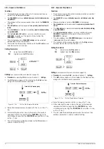
value for the selected parameter appears at the display.
This value can be increased <
↑
> or decreased <
↓
> within
predefined limits with the parameter adjusting keys.
Pressing the key briefly results in a single step, and if the
key is pressed and held the value is advanced through a
series of consecutive steps. The setpoint value is
changed simultaneously along with the display value.
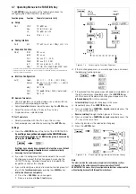
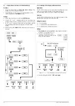
b) Selecting text parameters
(setting alternatives)
After selecting the function to be adjusted with the
<FUNCTION> key, the current parameter status appears
at the display in text format. Any of the alternative settings
can be selected by repeatedly pressing the <
↑
> or the
<
↓
> key. The parameter blinks at first to indicate that the
displayed alternative has not yet become effective. The
selected parameter value does not become effective until
it is acknowledged with the <ENTER> key. If
acknowledgement does not ensue, the device function is
exited and the respective setting remains unchanged.
c) Browsing through the SEQUENCE register
→
chapter 4.11 RCL and chapter 4.8 SELECT
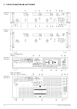
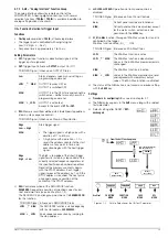
[17] Protective functions status display
These indicators provide information concerning the setting
status (yellow LED) or triggering (red LED) of protective
functions. Illumination of the respective LEDs has the
following significance:
OVP (overvoltage protection)
Overvoltage protection has been triggered, because output
voltage has exceeded the selected trigger value (OVSET).
The output is deactivated.
Causes:
– Voltage setpoint USET has been set too high manually, or
as a result of memory recall, programming error or Uset
control signal to the analog interface
– Voltage transients caused, for example, by switching
inductive power consumers (perhaps too little difference
between selected USET and OVSET values)
– During auto-sensing: Sensing lead polarity is reversed, or
an output lead is/was interrupted or was not taken into
consideration when adjusting OVSET, so that the voltage
at the output terminals which is relevant for the OVP
function is increased by the amount to be compensated
for at both leads, and is higher than USET voltage as
controlled by the sensors at the load side (too little
difference between selected USET and OVSET values).
– Unipolar power recovery from the connected power
consumer (e.g. DC motor)
– A device error or defect has occurred.
After the cause of triggering has been eliminated, the
output can be reactivated with the OUTPUT ON
command.
OTP (overtemperature protection)
Overtemperature protection has been triggered because the
device has overheated. The output is deactivated.
Causes:
– Impaired cooling, e.g. air inlet or exhaust vents are
obstructed.
– Excessive ambient temperature The device is capable of
continuously supplying nominal power at ambient
temperatures of up to 50° C (measured at the air inlet
vents). Approximately 120 to 130% nominal power can be
drawn intermittently (triggering point for electronic power
limiting). Continuous operation at these levels may cause
triggering of the overtemperature protection function.
– One or more fans have failed.
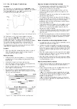
– Output “fluctuates”. In the case of complex loads, control
fluctuations may occur (
→
chapter 5.2) which result in
increased power loss and thus causes overheating.
– A device error or defect has occurred.
As long as the latter has no occurred, the output can be
reactivated after an adequate cool-down period. If the
POWER-ON function has been set to “RCL”, the output is
reactivated automatically.
OCP (overcurrent protection)
Overcurrent protection has been triggered because the
output has been operated in the current limiting mode
(current control) for a duration greater than the DELAY value
with activated OCP ON function.
Causes:
→
The output can be reactivated with the OUTPUT ON
command.
OCP ON
Overcurrent shutdown is enabled.
→
LOCAL LOCKED
The front panel controls are disabled, and are thus protected
against unauthorized or inadvertent adjustment.
This display only applies to disabling of the front panel
controls by means of manual adjustment or a control signal
applied to the TRIGGER input (for T_MODE TRG). It does
not indicate disabling of manual switching to local control by
means of the IEC bus LOCAL LOCKOUT command.
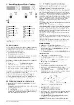
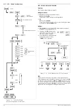
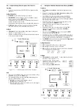
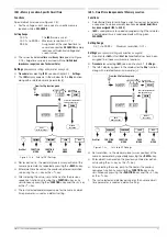
[18] Function selector key <FUNCTION>
No special key is assigned to device functions which are
normally seldom adjusted or used. These functions are set in
a menu-driven fashion by means of the following procedure:
1. Select the desired device function
with the <FUNCTION> key:
– Scroll forward:
<FUNCTION> + <
↓
> or
<FUNCTION> alone
– Scroll back:
<FUNCTION> + <
↑
>
→
Left display:
Device function code
→
Right display:
Currently selected parameter setting
or saved measured value
2. Select the desired function parameter
by (repeatedly) activating the <
↑
> or the <
↓
> key (
→
[16]
).
→
Left display:
Unchanged
→
Right display:
For adjusting the selected function
parameter (blinking indicates that
adjustment has not yet been executed)


