


GMC-I Gossen-Metrawatt GmbH
21
4
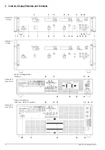
Manual Operation and Device Functions
Important menu functions can be selected directly with the
<SELECT> keys.
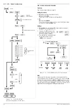
4.1 Menu Structure
After the power-up sequence has been completed, the device is
switched to the basic operating mode – indicated by the
illuminated READY LED – by means of which the device’s basic
functions can be executed, such as:
•
Select desired output voltage Uset
•
Select desired output current Iset
•
Adjust allowable working range with soft-limits Ulim and Ilim
•
Adjust overvoltage and overcurrent protection
Additional setup menus can be accessed with the function key.
These include:
•
SEt (setup)
Extended setup functions
•
AnIF (analog interface)
Analog interface settings
•
SEq (sequence function) Sequence function settings
•
bUS (computer interface)
Interface configuration settings
After selecting the desired setup menu with the function key, the
respective menu level appears at the display.
The function and arrow keys are used to scroll through the
respective menu levels and select the desired settings.
The CE/Local key can be used to shift back up one level at a
time, until the basic operating menu once again appears.
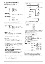
4.2 Setting Output Voltage Uset and Output Current Iset
There are two ways to set output voltage and output current:
•
Direct selection
Changes become immediately effective when this method is utilized,
assuming the output is active.
•
Pre-selected settings
Output voltage or current is preset with the arrow keys to the
desired value. The selected value is activated at the output
after acknowledging with the ENTER key.
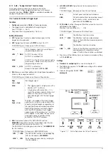
4.2.1
Direct Selection (rotary knobs and arrow keys)
The operating concept allows for direct selection of output
voltage and/or output current with the rotary knobs, with
immediate activation of the new values at the output.
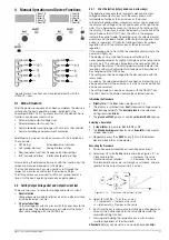
In the default configuration, momentary output values appear at
the display with voltage at the left and current at the right-hand
side. This is indicated by means of the two LEDs to the right of
the display. If the output is active (indicated by illumination of the
red LED above the OUTPUT key), the LEDs in the diagram
indicate the control mode. Depending upon the selected output
quantities and the load situation, either output voltage or output
current is regulated. CV (constant voltage) stands for voltage
regulation, and CC (constant current) stands for current
regulation.
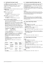
If the working point is not within the allowable control range, the
power LED lights up.
The display can be switched to a representation of the
corresponding setpoint by slightly turning one of the rotary knobs
(Uset or Iset). This change is indicated by the respective LED to
the right of the display. The blinking decimal place indicates the
resolution with which adjustment will take place. Resolution can
be changed with the RESOL key.
The setting can then be changed to the desired value with the
rotary knob.
As soon as the selected setpoints have been activated, they can
also be adjusted with the arrow keys, in which case resolution can
also be pre-selected.
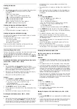
The setting mode can also be accessed with the SELECT key.
The LEDs next to the display indicate the selected function.
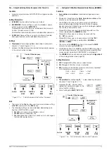
Initializing the Procedure
☞
Slightly turn
(1) the
Uset
!
The display is switched from
Uout
(measured voltage value) to
Uset
(voltage setpoint). The
decimal place
for the selected
setting resolution
blinks
.
!
The
green
Uout/V LED
goes out, and the
yellow
Uset/V LED
lights up.
Selecting a Resolution
!
3 step widths
are possible:
0.01 V
,
0.1 V
or
1 V
.
!
The
blinking decimal place
indicates which
step width
will be used for
setpoint adjustment.
☞
Repeatedly press the
<RESOL>
key [19] until the desired
decimal place blinks at the display.
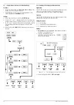
Executing the Procedure
!
Values become immediately active during adjustment.
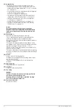
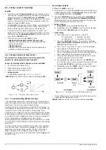
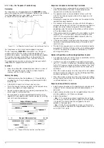
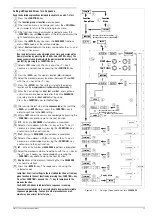
☞
Adjustment (2) with the
Uset
rotary knob (see Figure 4.2.1 a):
Clockwise rotation
→
Increases the value
Counterclockwise rotation
→
Decreases the value
All intermediate values are run through semi-linearly, and are
read out to the output (assuming it is active).
Figure 4.2.1 a
Continuous Adjustment of Uset
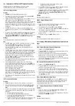
☞
Adjust (3) with the <
↑
> or the <
↓
> key:
<
↑
> (increment)
→
Increases the value
<
↓
> (decrement)
→
Decreases the value
!
Each time the key is pressed, output voltage is changed by an
amount which corresponds to the value selected with the
resolution setting function.
!
Pressing and holding the respective key results in rapid
scrolling, regardless of the step width.
Attention! Uset
may not be set to a value which exceeds
Ulim
!
Uout / V
Uset / V
Ulim / V
OVset / V
Pout / W
SELECT
Uset
Iset
Iout / A
Iset / A
Ilim / A
DELAY / s
Pout / W
SELECT
↑
↓
Pout/
OVset/
Ulim/
Uset/V
Uout/
Pout/
Delay/s
Ilim/A
Iset/A
Iout/A
OUTPUT
Uset / V
Ulim
t
(1)
(2)
(3)


