22
GMC-I Gossen-Metrawatt GmbH
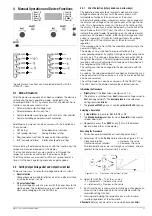
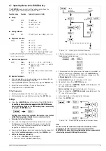
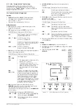
Uset – Selecting a Setpoint for Output Voltage
Function
•
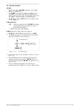
Adjustment with the
Uset rotary knob
[8] is not enabled until 0.4
seconds after the digital display [9] has been switched to the
respective function. This
delay time
prevents
inadvertent
changes
to
Uset
during selection of the
Uset
display. The rotary
knob must be adjusted after this time period has elapsed in
order to change the
Uset
setting.
•
After
delay time
has elapsed, output voltage is adjusted directly
as the knob is rotated if the output is active. The currently
active setpoint appears continuously at the display [9].
•
If no adjustment is made for a period of 10 seconds, the
display automatically returns to measured voltage value Uout.
The display can be
immediately switched
to the Uout value by
pressing the
<CE/LOCAL>
key.
•
There are two ways to adjust
Uset
manually:
–
Adjustment with immediate activation of the new value:
Adjustment of the setpoint has an immediate effect on
load output quantities.
–
Setpoint adjustment:
Adjustment of the setpoint does not effect load output
quantities until after activation.
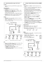
Iset – Selecting a Setpoint for Output Current
The procedure for selecting output current Iset is identical to the
procedure for selecting output voltage Uset (page 22).
However, the following controls and displays must be substituted:
•
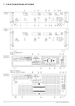
Iset rotary knob (chapter 3 [12])
•
Right-hand display (chapter 3 [13])
•
Yellow Iset/A LED (chapter 3 [14])
•
Setting resolution
:
3 step widths are possible: 0.01 A, 0.1 A or 1 A.
Attention:
Iset
may not be set to a value which exceeds
Ilim
!
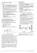
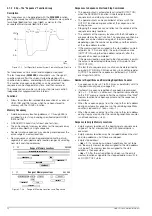
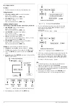
Figure 4.2.1 b
Continuous Adjustment of Uset
4.2.2
Pre-selected Setting (ENTER, arrow keys)
If the application requires that switching to a new setpoint takes
place in a single jump by pressing a key (without semi-continuous
adjustment), this can be accomplished as follows.
Proceed to the basic setting menu using the CE/LOCAL key, i.e.
to the display of momentary output values. Press the ENTER key
in order to switch to the pre-selection setting mode. After
switching to this mode, the currently valid setpoint values appear
at both displays (indicated by the LED to the right of the display).
As a default function, voltage adjustment is always activated first,
which is indicated by a blinking decimal place at the
corresponding display. Repeatedly press the ENTER key in order
to switch back and forth between current adjustment and voltage
adjustment.
The new setpoint can be selected with the arrow keys (and only
with the arrow keys), after selecting voltage or current setpoint
adjustment and the desired resolution. The SET LED blinks in
order to indicate that a change has been made but not yet
activated. The new setpoint is activated after acknowledging with
the ENTER key.
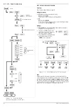
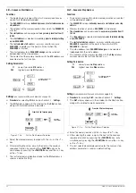
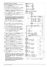
Pre-selecting a Setpoint
☞
Press
the
<ENTER>
key [15].
!
The display [5] is switched from
Uout
(measured voltage value)
to
Uset
(voltage setpoint). The
decimal place
which corresponds
to the selected resolution setting
blinks
.
!
The green
Uout/V LED
goes out, and the yellow
Uset/V LED
[6]
lights up (as long as the
Uset/V LED
is continuously illuminated
,
direct adjustment with immediate activation of the new value
can be executed with the rotary knob [7]).
•
Setting resolution
:
!
3 step widths
are possible:
0.01 V
,
0.1 V
or
1 V
.
☞
Repeatedly press the
<SELECT>
key [13] until the desired
decimal place (
step width
)
blinks at the display.
•
Output Voltage
:
☞
Press either the <
↑
> key or the <
↓
> key [11]!
<
↑
> (increment)
→
Increases the value
<
↓
> (decrement)
→
Decreases the value
!
The yellow
Uset/V LED
[5] blinks. This indicates that
new
values are displayed but not activated
during adjustment. The
old
Uset
value remains active.
☞
Press the <
↑
> key or the <
↓
> key [11] until the desired
value appears at the display [5].
!
Each time the key is pressed, the pre-selected setpoint
value is changed by an amount which corresponds to the
value selected with the resolution setting function.
!
Pressing and holding the respective key results in rapid
scrolling, regardless of the step width.
☞
Acknowledge the selected value with the
<ENTER>
key
[15]. The new value is now activated at the output [4], and
the yellow
Uset/V LED
[6] is continuously illuminated.
☞
Repeatedly press the <
ENTER
> key [15] in order to switch
back and forth between
Uset
and
Iset
.
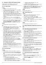
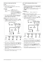
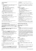
Figure 4.2.2 a
Adjusting Uset with a Specified Fixed Value
•
Output voltage jumps from the old value to the new value in a
single step (no intermediate values).
Attention:
Uset
may not be set to a value which exceeds
Ulim
!
Iset / A
Ilim
t
(1)
(2)
(3)
Uset / V
ENTER
ENTER
ENTER
Uout Iout
Select Uset
Uout unchanged!
CE/LOCAL
Uout Iout
Iout unchanged!
Activate
Select Iset
Uset


