24
GMC-I Gossen-Metrawatt GmbH
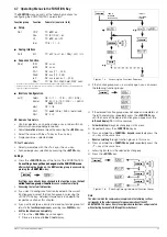
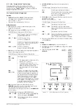
4.5 Description of OVP and OCP Protection Functions
Protection for the connected power consumer and the
KONSTANTER by means of the following functions:
OVP – overvoltage protection
Function
•
Protection
for the connected power consumer
•
If voltage at the output terminals exceeds the selected
OVSET
value, the power output is deactivated.
•
Triggering of overvoltage protection causes immediate (< 200
μ
s)
deactivation of the output (
OUTPUT OFF
). The HF power
transmitter is disabled, and the electronic sink for discharging the
output capacitors over a period of approximately 350 ms is
activated. In addition, bit 4 (OVPA) is set in event register A. Bit 4
remains set in status register A for as long as the trigger value is
exceeded.
•
The
OVP
LED lights up as soon as overvoltage protection is
triggered (see also chapter 3 [17]), and the
red OUTPUT
LED goes
out.
•
As soon as the shutdown condition no longer exists, the power
output can be reactivated by pressing the
<OUTPUT> key,
by
transmitting a
trigger signal
to the analog interface
or by means of
computer control
(“
OUTPUT
ON
”
➩
red
OUTPUT
LED lights up).
Settings
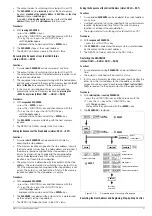
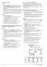
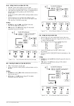
The setting procedure is described in chapter 4.8.1.
Note
•
The
OVP
trigger value (OVSET) should be set at least 1 V higher
that the desired
USET
output voltage in order to prevent
undesired triggering of the
OVP
function resulting from
overshooting due to sudden output discharging (minimum
values: chapter 1.5.3)!
•
The
OVP
trigger value makes reference to the prevailing voltage
value between the output terminals of the SSP. This voltage is
increased by the
USET
parameter during sensing mode operation
(remote sensing) by an amount equal to voltage drop at the
output leads. For this reason, the above defined difference
between
OVSET
and
USET
must be correspondingly increased
during sensing mode operation.
•
The triggering threshold for overvoltage protection is identical to
the displayed value, and is always active!
•
Overvoltage protection response time is less than 200 µs.
Output voltage generated by the device may exceed
OVSET
for
the duration of this response time. Maximum overshooting can
be approximately calculated as follows:
Uout = ISET [A] x 200 [µs] / Cout [µF]
ISET = selected current setpoint
Cout = capacitance of the output capacitor
Subsequent discharging time for the output capacitor depends
upon load, and corresponds to the specified values for response
time at Unom —>1 Volt included in chapter 1.5.3.
•
Possible causes for triggering overvoltage protection are listed in
chapter 3 [17].
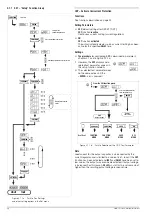
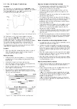
OCP – Overcurrent Protection
Functions
•
Protects
the power consumer from continuous overcurrent.
•
Deactivates the power output when load current
Iset
has been
reached, and the output is switched to the
current regulating
mode
.
•
Current can nevertheless be allowed to exceed Iset for specified,
short periods of time by specifying a delay time (see below), for
example:
!
Starting current for electric motors
!
In-rush current for capacitive power consumers
!
For testing the breaking performance of circuit breakers,
motor protecting switches, fuses etc.
!
For determining the short-term load capacity of contacts and
cables, as well as electrical and electronic components
!
In order to maintain short response times when
programming voltage increases
•
The red
OCP
LED lights up as soon as
OCP
is triggered (see also
red OUTPUT
LED goes out.
•
The power output can be reactivated at any time by pressing the
<OUTPUT> key,
by transmitting a
trigger signal
to the analog
interface
or by means of
computer control
(
OUTPUT
ON
➩
red
OUTPUT
LED lights up).
Settings
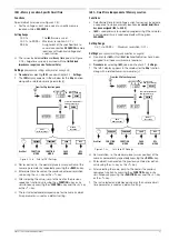
DELAY – Output Off Delay for OCP
Functions
•
Delay time prior to deactivation of the power output after
triggering of current regulating (
Iout = Iset)
•
Only enabled with activated
OCP
function (
OCP ON
)
•
If output current
Iout
drops below
Iset
before
DELAY
time elapses,
the shutdown sequence is aborted.
•
If current regulation is triggered again, the routine is started once
again (at 00.00).
•
The default setting after
RESET
(
*RST
) is 00.00.
Settings
The setting procedure is described in chapter 4.8.1.
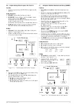
4.6 Display of Momentary Output Values Uout, Iout and
Pout
Uout – Display Momentary Measured Voltage Value
•
Appears at the
left-hand display
[9]
•
The
green Uout/V
LED [10] lights up and indicates display of the
momentary measured voltage value.
•
The measured voltage value is automatically displayed again
approximately 10 seconds after the last setting has been made.
•
The momentary measured voltage value is displayed
immediately if the user exits the device functions setting mode by
pressing the
<CE/LOCAL>
key [23].
Iout – Display Momentary Measured Current Value
•
Appears at the
right-hand display
[13]
•
The green
Iout/A
LED [14] lights up and indicates display of the
momentary measured current value.
•
The measured current value is automatically displayed again
approximately 10 seconds after the last setting has been made.
•
The momentary measured current value is displayed immediately
if the user exits the device functions setting mode by pressing
the
<CE/LOCAL>
key [23]
.
Pout – Display Momentary Output Power
Repeatedly press the
<SELECT>
key [11] or the
<SELECT>
key [15]
until the respective Pout LED lights up. Momentary output power,
based upon measured Uout and Iout values, appears at the
corresponding display ([9] or [13]).
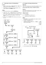
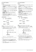
UI
_
– Display Measured Values in U/I Min-Max Memory
Functions
•
Reads out stored values for
Umin
,
Umax
,
Imin
and
Imax
at the
display, or via the computer interface.
•
Stored Min-Max values can be read out regardless of the status
selected for the
MINMAX
function.
Settings

