72
GMC-I Gossen-Metrawatt GmbH
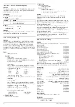
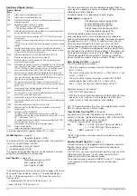
Assume that the event registers had an initial value of “0”. After
receiving an incorrect command, the device sets either bit 5
(command error CME) or bit 4 (execution error EXE) in the event
standard register ESR (see Figure 6.5). Accordingly, bits 4 and 5
must also be set in the respective ESE enable register, so that the
ESR group message can be forwarded to the status byte register
(STB). The corresponding SRE enable register must in turn be set
to TRUE (= 1) at bit 5, so that the MSS group message (master
summary status) can be generated by the ESR bit, after which it is
then entered to bit 6 of the status byte itself, and indicates that
there is at least one reason to generate an SRQ message. The
SRQ message is then triggered by the downstream service
request function.
The respective commands for setting the assumed SRQ
conditions are thus:
*ESE 48
;
*SRE 32
.
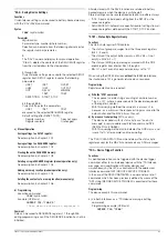
Service calls from the ERA and ERB event registers or the MAV
message are generated in the same way.
Comment
It is usually advisable to enable at least the following events for
SRQ message triggering, because even if only one of these
events occurs, the device is no longer capable of executing the
desired settings:
CME, command error
EXE, execution error
QYE, query error
OTPA, OTP activated
TSTE, self-test error
LIME, limit error
OVPA, OVP activated
OCPA, OCP activated
PHF, phase failure
SEQE, sequence error
OUTE, output error
DDTE, define device trigger error
The setting commands required to this end read as follows:
*ESE 52; ERAE 56; ERBE 190; *SRE 52.
The control computer may execute serial polling at the IEC bus in
response to the SRQ message (
→
chapter 6.2), in order to
pinpoint the affected device and determine the reason.
If all utilized devices with SRQ capability are equipped with parallel
polling as well, it may be possible to identify the device which
generated the SRQ message more quickly by means of this
function, assuming they have been configured accordingly.
The service request function is not available via the RS 232C
serial interface, but similar results can be obtained by querying
(either cyclically and/or after each data transmission to the device)
and evaluating the individual status message (IST) after previously
setting the parallel poll enable register (PRE) (
→
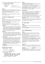
START_STOP, START_STOP? – Memory Location Start and Stop
Addresses for the SEQUENCE Function
Functions
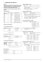
The parameters settings for START and STOP addresses define
the beginning and the end of the sequence to be executed. The
following applies: start address
≤
stop address.
Syntax
START_STOP
start address, stop address
Parameter
Start address, stop address
Parameter type: number (whole number)
Default setting after RESET (*RST): both unchanged
a) Manual Operation
See description on page 32 ff.
b) Programming
Set
Setting command:
STA
RT_STOP
start address, stop address
Example (HP Basic):
OUTPUT 712;"STA 20,115"
! Sequence start = register 20
! Sequence end = register 115
Setting query
Query command:
STA
RT_STOP
?
Response string:
START_STOP
start address,
stop address
Parameter format
start address, stop address
:
nnn
Fixed response string length: 18 characters
Example (HP Basic):
OUTPUT 712;"STA?"
ENTER 712;A$
DISP A$
→
Display:
START_STOP 020,115
Comment
In the case of programming via the interface, the start and stop
parameters are combined into a single unit: “START_STOP”. If an
attempt is made to set the start address to higher value than the
stop address, the command is not executed and bit 4 (EXE,
execution error) is set in the standard event register ESR.
Selected START and STOP address values are saved to setup
memory as a device setting with the SAVE command.
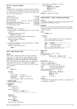
STORE, STORE? – Transferring Parameters Directly to Memory
Functions
•
The
STORE
command and its parameters can only be queried
via an interface with appropriate programming.
•
It immediately overwrites all values of the memory location with
the new parameter data.
•
Memory location contents are
not
shifted.
Note:
If more than 15 STORE commands are to be transmitted in
blocks, a string length of at least 25 characters per command is
recommended (see response format for STORE?).
Syntax
STORE
n, v1, v2, v3, txt
Parameter
n, v1, v2, v3, txt (memory address, USET,
ISET TSET, CLEAR / no function)
Parameter type:
integer, real, real, real, character
* ON, OFF and NC:
Setpoints are transferred, the text parameter is
set internally to NC.
Programming
Set
Setting command:
STO
RE
n, v1, v2, v3, txt
Example
(HP Basic):
OUTPUT 713;"STORE 14,15.5,3,9.7,NC"
{overwrite memory location 14 with
the following data:
Uset = 15.5 V; Iset = 3 A;
Tset = 9.7 s; no function}
Setting Range
Start address
11
through
255
Start address
Stop address
11
through
255
Stop address (
≥
start address)
Setting Range
n
11
through
255
Memory address
v1
0
≤
v1
≤
USETmax
v2
0
≤
v2
≤
ISETmax
v3
TSET: 00.01 [s]
≤
v3
≤
99.99 [s]
txt
CLR, NC*
CLR: deletes the entire memory
location regardless of other
data)

