GMC-I Gossen-Metrawatt GmbH
17
Note:
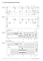
Numbers in brackets make reference to figures on page 19.
[1]
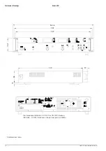
Rack mounting tabs (included accessories)
for mounting to a 19" rack
Assembly:
– Unscrew the handles at the front.
– Pull out the filler strips at the sides and replace them with
the included rack-mount fastening tabs.
– Replace the front handles.
[2]
Front handles
For carrying the device or pulling it from the 19" rack
The handles can be removed if desired (turn M4 screws with
a maximum length of 8 mm into the empty threaded holes).
[3]
Device feet
For use as a benchtop instrument
The device can be tilted back slightly by folding the front feet
out.
As a rule, the feet must be removed in order to install the
device to a 19" racks.
[4]
Mains switch
For turning the device on and off
After switching the device on, a self-test is performed with a
duration of approximately 8 seconds. After successful
completion of the self-test, the “POWER-ON” function
configures the device with predetermined settings and the
device is ready for use.
When the device is switched off, it is disconnected from
mains power and the output is immediately deactivated. The
last device configuration, as well as any settings which have
been saved to battery-backed configurations memory, are
retained.
[5]
POWER indicator lamp
Indicates that the device is switched on (power on).
[6]
Control mode display
The illuminated LED indicates the current operating status
(control mode) of the output, as long as it is active:
– Green “CV” LED lights up: constant voltage mode (Uout =
Uset),
– Green “CC” LED lights up: constant current mode (Iout =
Iset)
– Yellow “Pmax” LED lights up: electronic power limiting is
active (Pout > Pnominal)
– No LEDs illuminated: output is inactive
[7]
Output On-Off key <OUTPUT>
The power output can be activated and deactivated by
pressing the <OUTPUT> key. The respective LED is
illuminated as long as the output is active.
No significant output voltage overshooting occurs when the
output is activated and deactivated.
The output capacitor is rapidly discharged by a sink when
the output is deactivated. After approximately 350 ms (500
ms for 80 V models), the output becomes highly resistive,
but it is not isolated from the output terminals.
[8]
Rotary knob for adjusting voltage
Voltage is adjusted in the usual fashion with the rotary knob.
However, the adjusting element is not a potentiometer, but
rather a rotary pulse encoder which generates 24 pulses per
revolution, and whose step size per pulse (setting resolution)
can be adjusted to either coarse, medium or fine with the
<RESOL> key [19]. This allows for convenient, precise
adjustment on the one hand, and also assures that no
change occurs to the selected value when switching
between remote control and manual operation.
When the voltage adjusting knob is turned, the left display is
first switched to the Uset display and the current voltage
setpoint appears. After approximately 0.4 seconds, one of
the decimal places starts blinking at the display in order to
indicate the selected adjusting sensitivity. From this point on,
turning the rotary knob changes the display value, and thus
the setpoint value, at the selected decimal place. Clockwise
rotation increases the value, and counterclockwise rotation
decreases the value. If no adjustment is made for a period of
10 seconds, the display automatically returns to measured
voltage value Uout. The display can be immediately
switched to the Uout value by pressing the <ENTER> or the
<CE/LOCAL> key.
[9]
Left-hand display with
[10] Display parameter indicators and
[11] Display selector key <SELECT>
As a default setting, measured output voltage value Uout
appears in volts at the left-hand display. The display can be
switched to any of the following values by (repeatedly)
activating the respective <SELECT> key:
– Uset
= Output voltage setpoint in volts
– Ulim
= Upper setting range limit for Uset
– OVset = Trigger value for output overvoltage protection
in volts
– Pout
= Momentary measured output power in watts
(calculated as Uout x Iout)
The LEDs assigned to the display indicate the type of
displayed values (green LEDs = measured values, yellow
LEDs = setting values).
If no adjustment is made for a period of 10 seconds during
the display of a setting value, the display returns to Uout.
Measured power Pout can be indicated at the left, as well as
at the right-hand display. This makes it possible to evaluate
output power relative to output voltage or output current.
Additional device functions can be selected with the
<FUNCTION>, <SAVE> and <RCL> keys. The function
code appears at the left-hand display in this case.
“Err” appears as an identifier for system messages.
[12] Rotary knob for adjusting current <Iset>
The same applies to this rotary knob with reference to output
current, as is also the case with the voltage adjusting knob
[8]
.
[13] Right-hand display with
[14] Display parameter indicators and
[15] Display selector key <SELECT>
As a default setting, measured output current value Iout
appears in amperes at the right-hand display. The display
can be switched to any of the following values by
(repeatedly) activating the respective <SELECT> key:
– Iset
= Output current setpoint in amperes
– Ilim
= Upper setting range limit for Iset
– DELAY = Shutdown delay time for the OCP function in
seconds
– Pout
= Currently measured output power in watts
(calculated as Uout x Iout)
The LEDs assigned to the display indicate the type of
displayed values (green LEDs = measured values, yellow
LEDs = setting values).
If no adjustment is made for a period of 10 seconds during
the display of a setting value, the display returns to Iout.
Additional device functions can be selected with the
<FUNCTION>, <SAVE> and <RCL> keys. The respective
setting parameter or measured value appears at the right-
hand display in this case.
“Err” appears as an identifier for system messages (see
chapter 8.6).
[16] Parameter adjusting keys
<
↑
>
and
<
↓
>
In order to prevent operator errors to the greatest possible
extent, the two rotary knobs,
[8]
and
[12]
, are used
exclusively for adjusting output voltage and output current.
These two keys are used for the selection and adjustment of
parameters for all other adjustable device functions
according to the following method:
a) Adjusting numeric parameters
After selecting the function to be adjusted with the
<SELECT>, <SAVE> or <RCL> key, the current numeric


