48
GMC-I Gossen-Metrawatt GmbH
5
Analog Interface
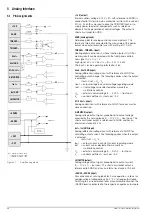
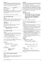
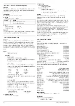
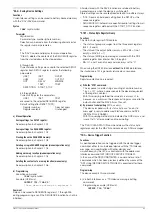
5.1 Pin Assignments
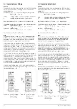
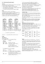
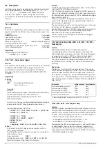
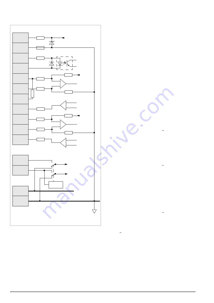
Figure 5.1
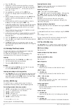
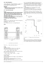
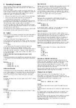
Auto-Sensing Mode
+15 V (output)
Internal auxiliary voltage (+15 V
±
3% with reference to AGND) is
connected to this terminal via a protective resistor with a value of
510
Ω
. It can thus be used to drive the TRIGGER input, or to
supply power to external components such as reference
elements for the generation of control voltages. The output is
short-circuit proof to AGND.
AGND (analog ground)
Reference point for analog control inputs and outputs. This
terminal is internally connected to the minus pole of the power
output via an auto-reversible fuse with a rating of 110 mA.
, TRIGGER– (input)
Floating digital control input, whose function (output On/Off or
memory recall) can be selected with the front panel controls.
Low signal: 0 V
≤
U
s
≤
1 V
High signal: 4V
≤
U
s
≤
26 V, Is = (U
s
– 2 V) / 1.5 k
Ω
The input is reverse-polarity protected to –26 V.
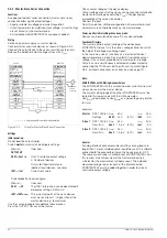
Uset+, Uset GND (input)
Analog (differential) voltage input with reference to AGND for
controlling output voltage. The following applies when the output
is activated:
Uout = Uset + U
su
* k
u
Uout = output voltage in constant voltage regulating mode
Uset = Uset voltage value selected either manually or
via interface control
U
su
= external control voltage (0 ... 5 V 0 ... Uout nom)
k
u
= control coefficient = Uout nom / 5 V
M / S Uset+ (input)
Analog control input with reference to AGND for series master-
slave connection.
U-MONITOR (output)
Analog voltage output signal, proportional to output voltage
acquired by the sensing leads (0 ... 10 V
0 ... Uout nom). The
short-circuit proof output is referenced to AGND and has an
internal resistance of 5 k
Ω
.
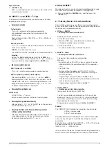
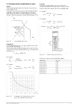
Iset+, Iset GND (input)
Analog (differential) voltage input with reference to AGND for
controlling output current. The following applies when the output
is activated:
Iout = Iset + U
si
* k
i
Iout
= output current in constant current regulating mode
Iset
= current value selected either manually or
via interface control
U
si
= external control voltage (0 ... 5 V 0 ... Iout nom)
k
i
= control coefficient = Iout nom / 5 V
I-MONITOR (output)
Analog voltage output signal, proportional to output current
(0 ... 10 V
0 ... Iout nom). The short-circuit proof output is
referenced to AGND and has an internal resistance of 9.3 k
Ω
.
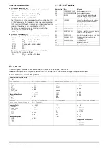
+SENSE, –SENSE (input)
For connection of sensing leads for 4-wire operation – allows for
compensation of voltage drops (to 2 * 2 V) at long output leads.
Switching to 4-wire operation takes place automatically when the
–SENSE lead is connected to the respective negative output pole.
+15 V
AGND
T
TRIGGER–
Uset +
Uset GND
M/S Uset +
U-MONITOR
Iset +
+SENSE
10 k
1.5 k
9 k 3
10 k
+OUT
–OUT
R1 = 80 k
Ω
for 40 V models
= 104 k
Ω
for 52 V models
510
110 mA
18 V
+15 V
Uset int.
10 k
10 k
Uset int.
Iset GND
I-MONITOR
–SENSE
Sense
Control
U-Monitor
5 k
R 1
= 160 k
Ω
for 80 V models
=
=
=
=

