GMC-I Gossen-Metrawatt GmbH
55
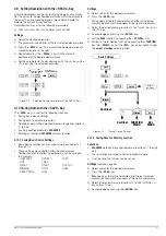
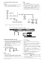
5.9 Series Connection
If output voltage from a single KONSTANTER is insufficient, or if
you want to generate a ± voltage, the outputs of several
KONSTANTERs can be connected in series.
WARNING!
Maximum allowable cumulative voltage for series connection is 120 V
(or 240 V with grounded neutral point).
5.9.1
Direct Series Connection
Caution!
If outputs with differing nominal values are series connected, the highest
selected current value is present at all outputs in the event of short-
circuit. However, the internal reverse-voltage protection diode is only
rated for nominal current of the respective device (see reverse voltage
withstand under Electrical Data).
For this reason, all current setpoints must be set to the lowest nominal
current value of all interconnected devices.
The ILIM parameter is used to select this setting.
Functions
The easiest way to supply the consumer with more voltage than is
available from a single KONSTANTER.
Easy wiring.
Less suitable for the constant current regulating mode.
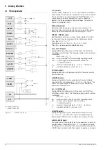
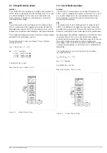
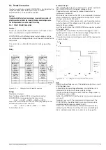
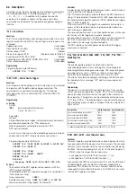
Wiring
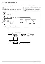
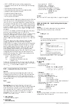
Figure 5.9.1a
Wiring for Direct Series Connection
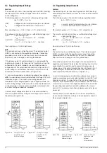
Settings
Deactivate all outputs.
Adjust the current setpoint ISET of all series connected
KONSTANTERs to approximately the same value:
Iset
= ISET1 = ISET2 = ISET3 = ISETn
Adjust the voltage setpoints USET such that they add up to the
desired cumulative voltage value Uset:
Uset
= USET1 + USET2 + USET3 + ... + USETn
Activate the outputs.
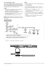
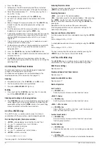
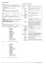
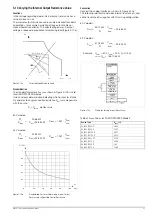
Functional Principle
The sum of all individual output voltages is made available to the
power consumer.
If load resistance is continuously reduced, all of the outputs
deliver the same load current at first.
When load current reaches the lowest selected current setpoint
value, current regulating is triggered at the respective output.
If load resistance is further reduced, this output maintains
constant load current until its output voltage has dropped to 0 V.
If even further reduction of load current occurs, the affected
output is forced by the other outputs to generate a negative
voltage.
As of approximately – 0.5 V, the internal reverse-voltage
protection diode becomes conductive.
Load current can once again climb, until current regulation is
activated at the output with the next highest current setpoint
value.
This procedure is continued until load current triggers current
regulating at the output with the highest current setpoint value.
Current is held constant by this last output until short-circuiting
occurs.
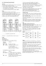
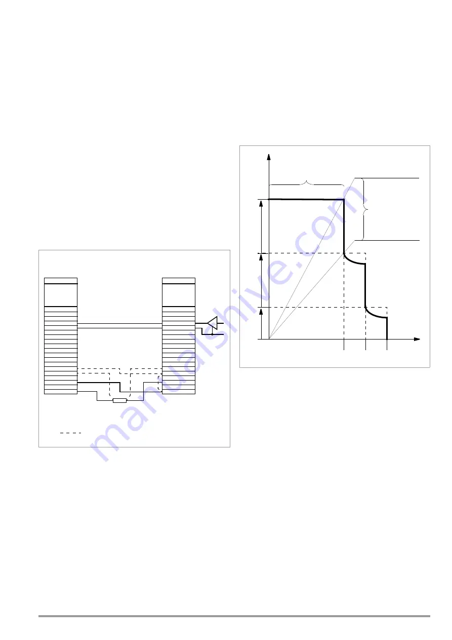
Figure 5.9.1b
U / I Diagram for Direct Series Connection
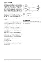
Note
Outputs can be simultaneously activated and deactivated by
connecting the TRG inputs (setting: trG out) in parallel (Figure
5.9.1a, optional connection) or in series (see also page 74).
Analog Interface
+15 V
AGND
T
TRIGGER
−
Uset +
Uset GND
M/S Uset +
Settings:
USET1+2 = Uset
ISET = Iset
OUTPUT on/off
SSP KONSTANTER
−
SENSE
+SENSE
U-MONITOR
Iset +
Iset GND
+OUT
I-MONITOR
–OUT
Device 2
Analog Interface
+15 V
AGND
T
TRIGGER
−
Uset +
Uset GND
M/S Uset +
Settings:
USET1+2 = Uset
ISET = Iset
OUTPUT on/off
SSP KONSTANTER
−
SENSE
+SENSE
U-MONITOR
Iset +
Iset GND
+OUT
I-MONITOR
–OUT
Device 1
= only required for sensing mode operation
Load
Optional
Connection
Ideal working range
for current regulation
at the load
Ideal working range
for voltage regulation
at the load
U
out1
U
out2
U
out3
I
out1
I
out2
I
out3
R
L
R
L


