56
GMC-I Gossen-Metrawatt GmbH
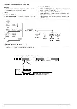
5.9.2
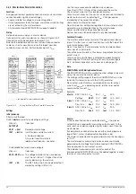
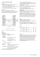
Master-Slave Series Connection
Functions
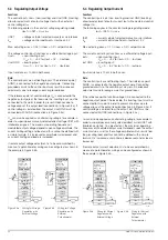
As opposed to direct series connection, master-slave series
connection offers significant advantages:
– Equally suitable for voltage and current regulation
– Output parameters (cumulative output voltage, current limiting)
are set entirely by the master device.
– All interconnected KONSTANTERs are equally loaded.
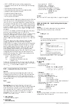
Wiring
Define one power supply as a master device.
Connect master and slave devices as shown in Figure 5.9.2.
Connect the output leads to the series circuit phase terminals.
Balance the individual output voltage values with R
sym
.
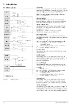
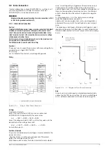
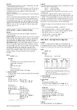
Figure 5.9.2
Wiring for Master-Slave Series Connection
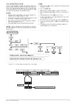
Settings
Initial power-up:
Do not load the outputs (idle).
Switch
master
on (mains) and configure settings:
(
Pon rcl)
If desired
OUTPUT
off
USET =
Uset / n
Uset: Cumulative output voltage
n: Number of devices
Only valid if nominal data are
identical for all devices, see notes
ISET =
Iset
Current limit value
Switch
slave 1
on and configure:
(
Pon rcl)
If desired
USET =
0
V
The
USET rotary knob can be deactivated if
desired by setting ULIM to 0 V.
ISET > ISET
master
The current setpoint at the slave devices
must be set at least 1% higher than at the
master device, e.g. to maximum.
Use the same procedure for additional slave devices.
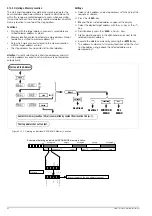
Press the OUTPUT ON key at the master.
Check output voltage at the device displays.
Output voltage at each of the slaves can be precisely matched to
master output voltage by adjusting R
sym
. Changes appear
immediately at the respective display.
Connect the load.
From this point on, setting and regulation of (cumulative) output
parameters are controlled entirely by the master device.
Power-up after initial settings have been made:
Devices can be switched on and off in any desired order.
Functional Principle
The master controls output voltage of the downstream
KONSTANTER (slave 1) via the slave’s voltage control input with
the help of the voltage monitoring signal.
In the same way, slave 1 functions as a master for the next
downstream device (slave 2) and so forth. Cumulative output
voltage is thus always proportional to master output voltage.
Outputs can be simultaneously activated and deactivated by
connecting the TRG inputs (setting: trG out) in parallel (Figure
5.9.2, optional connection) or in series (see also page 74).
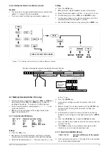
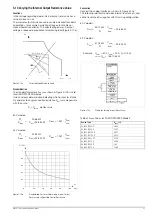
Note:
KONSTANTERs with Differing Nominal Values
The KONSTANTER with the smallest nominal current value must
always be used as the master device.
The current setting range of the other KONSTANTERs must be
limited to this lowest value with the ILIM parameter.
Uout
Slave
corresponds to Uout
Master
as a percentage only, relative
to U
nom
.
Example:
General
If analog interface connector cables and the sensing leads are
longer than 1 meter, shielded cable should be used. The shield is
connected to the ground terminal on the housing, or to –OUT.
The same current value is available from all KONSTANTERs. For
this reason, current measured at the master device only is
sufficient for the measurement of load current. The individual
measured voltage values for each of the interconnected
KONSTANTERs must be added together in order to arrive at
cumulative output voltage.
= only required for sensing mode operation
Analog Interface
+15 V
AGND
T
TRIGGER
−
Uset +
Uset GND
M/S Uset +
Settings:
USET = 0 V
ISET > Iset master
OUTPUT on
SSP KONSTANTER
−
SENSE
+SENSE
U-MONITOR
Iset +
Iset GND
+OUT
I-MONITOR
–OUT
SLAVE
Analog Interface
+15 V
AGND
T
TRIGGER
−
Uset +
Uset GND
M/S Uset +
Settings:
USET = Uset / 2
ISET = Iset
OUTPUT on/off
SSP KONSTANTER
−
SENSE
+SENSE
U-MONITOR
Iset +
Iset GND
+OUT
I-MONITOR
–OUT
MASTER
POWER_ON rcl
Load
R
sym
≈
10 K
Ω
Optional
Connection
Master
:
SSP 1000-80 U
nom
80 V
I
nom
25 A
Settings:
USET:
24 V
(30%)
ISET
:
3 A
Slave 1
: SSP 1000-52 U
nom
52 V
I
nom
50 A
Results in
Uout:
15.6 V
(30%)
Iout
:
3 A
Slave 2
: SSP 1000-52 U
nom
52 V
I
nom
50 A
Results in
Uout:
15.6 V
(30%)
Iout
:
3 A


