6
GMC-I Gossen-Metrawatt GmbH
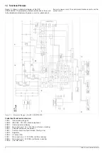
1.4 Functional Principle
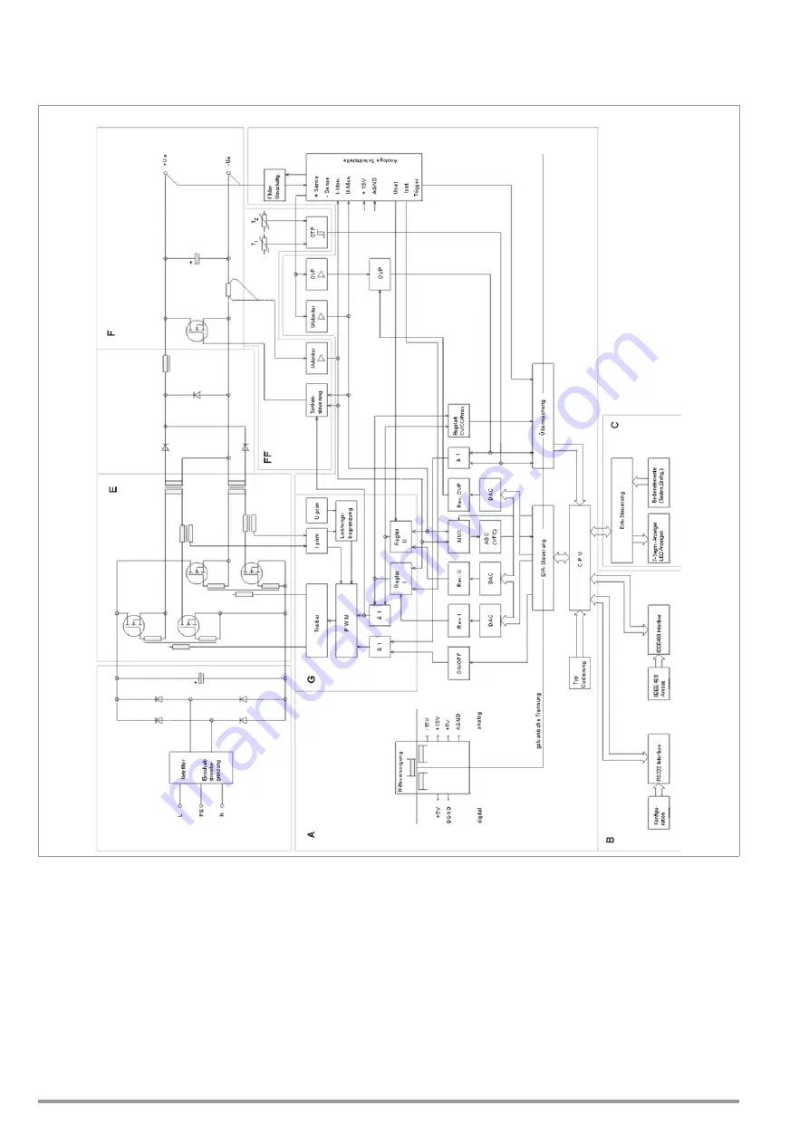
Figure 1.4 shows a schematic diagram of the SSP-
KONSTANTER. The delineations indicate distribution of the circuit
to the individual printed circuit boards, as well as subdivision of
the mains power circuit, the control and interface circuit, and the
output circuit.
Figure 1.4
Schematic Diagram of the SSP KONSTANTER
Printed Circuit Board Functions Overview
PCB A:
Central processing unit
PCB B:
IEEE 488 – RS 232C interface (optional)
PCB C:
Control panel and display
PCB D:
Mains input circuit, 0.5 / 1 KW (filter, rectification, screening)
PCB E:
Chopper and power transformer
PCB F:
Power output circuit (rectification, filtering, sink)
PCB G: Regulator
PCB H: HF output filter
PCB I:
Mains input circuit, 2 / 3 KW (filter, rectifier, screening)
PCB K:
Mains input circuit, 3 KW (filter, rectification, screening)
PCB M:
Line filter choke
62 N:
D
64 N: I
+K+M


