background image

74 

GMC-I Gossen-Metrawatt GmbH

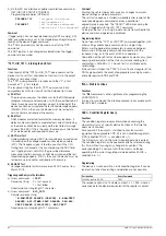
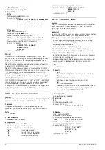
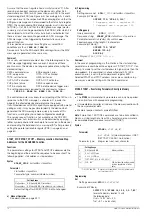
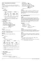
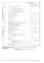
T_MODE, T_MODE? – Trigger Input Function Selection 

Functions

The T_MODE parameter assigns the floating trigger input with 
optocoupler (at the analog interface) to a selected device 
function.

Syntax

T_MODE 

action

Parameter

Action

Selection can be made from any of the following text 
parameters:

A detailed description of trigger input functions is included in 
chapter 5.7.

a)  Manual Operation

See description on page 29.

b) Programming

Set

Setting command:

T_M

ODE


action

Example (HP Basic):

OUTPUT 712;"T_MODE LLO"


! Trigger input causes control panel
! disabling / enabling.

Setting query

Query command:

T_M

ODE

?

Response string:

T_MODE


action

Possible response parameters for 

action

:

OFF


OUT

RCL


SEQ

LLO


MIN

Fixed response string length: 10 characters

Example (HP Basic):

OUTPUT 712;"T_MODE?"
ENTER 712;A$
DISP A$

Display: 

T_MODE LLO

Comment

The status of the T_MODE function is not saved as a device 
setting with the “SAVE” command. 

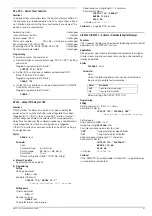
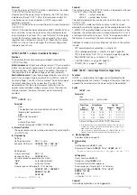
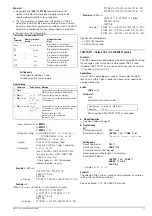
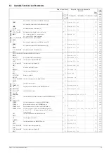
TSET, TSET? Dwell Time Specific to Memory Location for the 
SEQUENCE Function 

Functions

The TSET parameter setting defines memory location-specific 
dwell time for a voltage-current value pair to be recalled. If no 
specific value or a value of 00.00 [s] is assigned to TSET, TDEF is 
used as a default value for execution of the sequence function.

Syntax

TSET 

value

Parameter

Value

Parameter type: real number

Default setting after RESET (*RST): 0 (= TDEF)

a)  Manual Operation

See description on page 31.

b) Programming

Set

Setting command:

TS

ET


value

Example (HP Basic):

OUTPUT 712;"TSET 0.2"

! Specific dwell time: 0.2 seconds

Setting query

Query command:

TS

ET

?

Response string:

TSET


value

Parameter format 

value

nn.nn

Fixed response string length: 10 characters
Example (HP Basic):

OUTPUT 712;"TSET?"
ENTER 712;A$
DISP A$

Display: 

TSET 00.20

Comment

Dwell times of greater than 99.99 seconds per setting can be 
achieved if total dwell time is distributed to several consecutive 
sequence registers with identical current and voltage settings.
If the selected dwell time for a specific sequence register needs to 
be read out, the respective register must first be queried from 
memory with the RCL function.
The selected TSET value is also saved to the setup register as a 
device setting with the SAVE command.

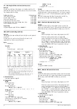
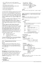
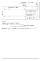
Action

Description

OFF

Trigger input function deactivated

OUT

Trigger input acts upon the OUTPUT: output On/Off

RCL

RECALL: memory recall (single step)

SEQ

SEQUENCE: sequential memory recall 
(SEQUENCE GO)

 a)

a. If the SEQUENCE function has not first been initialized, an active trigger signal

results in error message “Err 27”, which is displayed for approximately 1
second, and bit 5 (SEQE) is set in event register B (ERB). “RCL” or “SEQ”
settings can only be executed if the SEQUENCE function has been fully
initialized (see page 71).

LLO

LOCAL LOCKED: control panel disabling

MIN

MINMAX: Min-Max memory for measured values

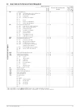
Default setting after RESET (*RST): unchanged

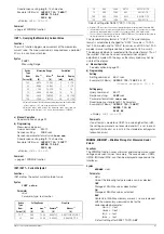
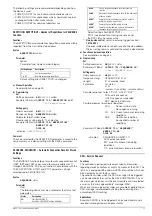
Setting Range:

(= TDEF) or

00.01

 [s] – 

99.99

 [s]

Resolution:

10 ms

Summary of Contents for 62 N Series

Page 1: ...Operating Instructions 3 349 262 03 4 8 06 Series 64 N Series 62 N SSP KONSTANTER 62 N and 64 N Series SSP 500 SSP 1000 SSP 2000 and SSP 3000 Programmable Power Supplies ...

Page 2: ...2 GMC IGossen MetrawattGmbH ...

Page 3: ...ta Upon Execution of RCL 40 4 9 Setting Resolution with the RESOL Key 41 4 10 Storing Data with the SAVE Key 41 4 10 1 Saving Basic Device Settings 41 4 10 2 Saving Data to a Memory Location 41 4 10 3 Clearing the Contents of a Defined Memory Range 42 4 10 4 Inserting a Memory Location 43 4 10 5 Deleting a Memory Location 44 4 10 6 Deleting the Contents of a Memory Location 45 4 11 Memory Recall w...

Page 4: ...ide of the KONSTANTER or disconnection of the protective conductor terminal may transform the KONSTANTER into a source of potential danger Intentional interruption is prohibited 62N The device is connected to the mains by means of a 3 conductor cable with mains plug The plug may only be inserted into a suitable outlet with earthing contact This safety precaution must not be defeated though the use...

Page 5: ...Function selection for trigger input Round off measured value for display Service request masks SRQ masks 1 Activate deactivate digital displays 1 Self triggering when mains power is switched on 1 Retrievable information Momentary measured voltage and current values Minimum and maximum measured voltage and current values Momentary output power Current device settings individual or complete Current...

Page 6: ...c Diagram of the SSP KONSTANTER Printed Circuit Board Functions Overview PCB A Central processing unit PCB B IEEE 488 RS 232C interface optional PCB C Control panel and display PCB D Mains input circuit 0 5 1 KW filter rectification screening PCB E Chopper and power transformer PCB F Power output circuit rectification filtering sink PCB G Regulator PCB H HF output filter PCB I Mains input circuit ...

Page 7: ...inal Measuring Procedure Monitor amplifier output signals which are proportional to actual output voltage and current are fed to an analog multiplexer MUX which switches one of the two signals to the input of the analog digital converter ADC depending upon the desired measured quantity The ADC functions in accordance with the synchronous voltage frequency conversion principle and makes a square wa...

Page 8: ...ampling rate Approx 2 measurements per second Power Supply Line voltage 62 N 230 V 10 15 47 63 Hz 64 N 3 x 400 230 V 10 15 47 63 Hz Inrush Current Max 50 AS Fuse 62 N 1 ea M 15 A 250 V 6 3 x 32 mm UL 64 N 3 ea M 15 A 250 V 6 3 x 32 mm UL Electrical Safety Safety class I Overvoltage category II for mains input I for output and interfaces Fouling factor 2 Earth leakage current 62 N 3 mAeff 64 N 1 mA...

Page 9: ...or M8 screws and 4 mm diameter drill holes Analog interface 14 pin plug connector with screw clamps Interface Options a RS 232C b IEEE 488 RS 232C RS 232C interface option a b 9 pin subminiature connector socket DIN 41652 Connector Pin Assignments Pin 2 TXD transmit data Pin 3 RXD receive data Pin 5 GND ground Figure 1 5 2 Connector Cable for Serial Interface IEC 625 IEEE 488 Interface option b 24...

Page 10: ...en Metrawatt GmbH Dimensional Drawings Series 62 N 449 465 482 6 500 40 88 13 76 2 Slot for optional IEEE 488 RS 232C or RS 232C interface IEEE 488 RS 232C interface is shown here part no K382A All dimensions in mm ...

Page 11: ...GMC I Gossen Metrawatt GmbH 11 Series 64 N 40 500 101 6 449 465 482 6 13 177 All dimensions in mm Shown with optional RS 232C interface part no K383A ...

Page 12: ...inal load 80 mV 6 ms 12 5 ms 150 ms 12 5 ms 80 mV 6 ms 12 5 ms 150 ms 12 5 ms 80 mV 6 ms 12 5 ms 150 ms 12 5 ms 80 mV 6 ms 12 5 ms 150 ms 12 5 ms Output capacitor discharging circuit Nominal value Power 2000 µF 25 W 2000 µF 25 W 4000 µF 50 W 6000 µF 75 W Measuring Function Measuring Range Voltage Current Power 2 666 58 770 V 0 48 26 68 A 0 550 W 2 666 58 770 V 1 92 53 37 A 0 1100 W 2 666 58 770 V ...

Page 13: ... V No load nominal load 160 mV 5 ms 15 ms 300 ms 15 ms 160 mV 5 ms 10 ms 300 ms 15 ms 160 mV 5 ms 10 ms 300 ms 15 ms 160 mV 5 ms 10 ms 300 ms 15 ms Output capacitor discharging circuit Nominal value Power 2000 µF 25 W 2000 µF 25 W 4000 µF 50 W 6000 µF 75 W Measuring Function Measuring Range Voltage Current Power 4 00 88 16 V 0 48 13 34 A 0 550 W 4 00 88 16 V 0 96 26 68 A 0 1100 W 4 00 88 16 V 1 92...

Page 14: ...conductor PE Protective conductor The cable must be secured with the cable clamp 38 for reliable strain relief 2 1 4 Connecting Power Consumers The output leads are connected to the output terminal bars 33 at the rear panel by means of ring type cable lugs The terminal bars are equipped with drill holes for M8 screws to this end 4 mm drill holes are included as well which can be used for connectin...

Page 15: ...elected device address 0 to 30 even after repeatedly switching the device on and off with abbreviated self test the device is probably defective If this is the case contact your local representative Abbreviated Power Up Test In order to shorten power up time or if problems occur with the normal power up test an abbreviated power up test can be used With the device switched off press and hold the E...

Page 16: ...stalling optional interfaces Shown with optional IEEE 488 RS 232C interface 1 2 3 4 5 6 7 8 9 10 11 12 13 14 15 16 17 18 19 20 21 22 23 24 25 26 31 37 36 35 34 33 32 26 31 32 35 36 37 38 34 33 27 30 8 Series 64 N 19 Rack Series 62 N Rear Panel Series62N 19 Rack Series 64 N Rear Panel 1 ...

Page 17: ...t on turning the rotary knob changes the display value and thus the setpoint value at the selected decimal place Clockwise rotation increases the value and counterclockwise rotation decreases the value If no adjustment is made for a period of 10 seconds the display automatically returns to measured voltage value Uout The display can be immediately switched to the Uout value by pressing the ENTER o...

Page 18: ...se of triggering has been eliminated the output can be reactivated with the OUTPUT ON command OTP overtemperature protection Overtemperature protection has been triggered because the device has overheated The output is deactivated Causes Impaired cooling e g air inlet or exhaust vents are obstructed Excessive ambient temperature The device is capable of continuously supplying nominal power at ambi...

Page 19: ...by pressing and holding the CE LOCAL key and simultaneously activating the ENTER key This command returns most device functions to their predefined default settings Default settings are described in chapter 4 16 and on page 62 4 Disabling front panel controls By pressing and holding the CE LOCAL key and simultaneously activating the RCL key all control panel elements are disabled except for the ma...

Page 20: ...a floating output and can be grounded with the positive or the negative pole A detailed functional description of the output and possible connection options is included in chapter 5 The outputs of all device models are classified as safety low voltage circuits SELV by the specified electrical safety regulations voltage in the event of error 120 V However contact protection measures are required fo...

Page 21: ... output voltage or output current is regulated CV constant voltage stands for voltage regulation and CC constant current stands for current regulation If the working point is not within the allowable control range the power LED lights up The display can be switched to a representation of the corresponding setpoint by slightly turning one of the rotary knobs Uset or Iset This change is indicated by...

Page 22: ...tage adjustment is always activated first which is indicated by a blinking decimal place at the corresponding display Repeatedly press the ENTER key in order to switch back and forth between current adjustment and voltage adjustment The new setpoint can be selected with the arrow keys and only with the arrow keys after selecting voltage or current setpoint adjustment and the desired resolution The...

Page 23: ...an be limited in order to assure ideal matching to the working ranges of the connected power consumer The Ulim and Ilim setting functions are provided to this end Setting options can be selected with the respective SELECT key Setting resolution is selected with the RESOL key The setting itself is entered with the arrow keys New settings become immediately active Attention These settings represent ...

Page 24: ... output is switched to the current regulating mode Current can nevertheless be allowed to exceed Iset for specified short periods of time by specifying a delay time see below for example Starting current for electric motors In rush current for capacitive power consumers For testing the breaking performance of circuit breakers motor protecting switches fuses etc For determining the short term load ...

Page 25: ...ssed automatically Accessing the last edited function If you want to configure a function included in the current function group select the function group by pressing the FUNCTION key Detailed information is included in the respective section of this chapter If you want to configure a function from another function group first return to the function group menu by pressing the CE LOCAL key Exit the...

Page 26: ...active until the ENTER key is pressed Figure 4 7 1 b Path to Selection of the OCP Text Parameter Note Load current for the output capacitor is also acquired by the current regulator and is limited to a value of Iset load If the OCP function has been activated and ISET and DELAY have been set to low values the output may even be deactivated if output voltage is increased For this reason DELAY must ...

Page 27: ...put when changing devices under test Stored values are then no longer updated nor are they automatically reset Stored Min Max values can be read out regardless of the status selected for the MINMAX function Stored Min Max values can always be reset with the UI_ RST command Stored Min Max values can also be reset with the RST command or with the key combination CE LOCAL ENTER RESET The status of th...

Page 28: ...d due to the application e g in manufacturing which may cause unnecessary concern Functions The ROUND function defines how many decimal places will be displayed for measured Uout and Iout values Setting Parameters 0 no rounding 1 rounded off by one decimal place 2 rounded off by two decimal places Settings The procedure for configuring Rnd is described in principle in chapter 4 7 and in Figure 4 7...

Page 29: ...TPUT is in the OFF state and cannot be switched on neither manually nor with a programming command HIGH _ LOW OUTPUT is activated Except in the event of OTP or OVP TRIGGER Signal Influence on Step by Step Control Edge Low High Start trigger signal HIGH The trigger signal is a high pulse with a duration of 11 to 800 ms A high pulse with a duration 1 0 s resets the address counter to the start addre...

Page 30: ... ended or can be started over again at the start address depending upon the number of repetitions and the contents of the stop address location If the memory location assigned to the stop address contain setpoints i e if it is not empty the output remains active OUTPUT ON using the stop address setpoints after the sequence has been completed If the memory location assigned to the stop address is e...

Page 31: ... in a sequence to whose memory locations no special dwell time has been assigned tSEt 00 00 tdEF is used primarily to speed up programming if the value for a certain dwell time is used repeatedly within a given SEQUENCE Setting Range 0 01 s to 99 99 s Maximum resolution 0 01 s Settings see sequence settings and execution on page 35 Do not enter tdEF until all Uset Iset and tset values have been as...

Page 32: ...s a default setting StoP Sequence Stop Address Functions The end of a range within which memory locations or content will be deleted or added The SEQUENCE is always defined by means of a start address and a stop address Memory location at which a SEQUENCE will be ended The stop address can correspond to any memory location from 11 to 255 The stop address is selected immediately prior to initially ...

Page 33: ... or by means of computer control page 71 1 255 Number of possible repetitions Settings see sequence settings and execution on page 35 Procedure for selecting rEP see also chapter 4 7 Settings The rEP display appears in the window for the SEq function along with a related numeric parameter s Figure 4 7 3 5 a Path to rEP Setting Select the desired number of repetitions with the key or the key After ...

Page 34: ...ontrol Acknowledge your selection with the ENTER key Figure 4 7 3 g Preparing for Step by Step Control The first valid memory location is now executed and the values saved to this location Uset and Iset are read out to the power output and the signal output The READY LED blinks slowly Figure 4 7 3 h Preparing for Automatic SEQUENCE Control In this case all memory locations are executed one after t...

Page 35: ...tting 14 Enter a tdEF value if necessary acknowledge by pressing the FUNCTION key and or jump to the next function 15 Strt Entry of a SEQUENCE start address is prompted 16 Select a start address with the key or the key if necessary acknowledge by pressing the FUNCTION key and or jump to the next function 17 StoP Entry of a SEQUENCE stop address is prompted 18 Select a stop address with the key or ...

Page 36: ...ory location are executed Selected dwell times of the exited and the new memory address are not taken into consideration The output retains its previous switching status output On or Off When jumping from the start address to the stop address or back again the remaining repetitions counter rrep remains unchanged Procedure With suspended SEQUENCE press the ENTER key next address or the key next add...

Page 37: ...on The output status is determined by the contents of the stop address The output retains its switching status output On or Off if the memory location assigned to the stop address is not empty The output is switched to the off status if the memory location assigned to the stop address is empty Procedure With suspended SEQUENCE press the FUNCTION key and then browse with the key the key or the FUNC...

Page 38: ...The READY LED blinks slowly in the HOLD status 4 7 4 buS The Interface Function Group The KONSTANTER can be set up for data transmission to a computer in the interface configuration function group In this case all of the settings previously selected with DIP switches are entered via menu functions The serial port RS 232 or the parallel port IEEE 488 is used for communication Addr Selecting the Dev...

Page 39: ...bits Figure 4 7 4 c Path to Selection of the dbit Text Parameter Pbit Setting the Parity Bit RS 232C Parity or check bits are used to detect transmission errors They are added to the character string so that the sum of H or L is even or odd as defined The parity bit can be set to one of the following values none no parity bit ZEro always 0 EVEn even numbered odd odd numbered nonE always 1 A parity...

Page 40: ...t doesn t matter whether the SEQUENCE function is in the RUN or the HOLD status Uout Iout Measured voltage and current values Uset Iset Voltage and current setpoints Pout Pout Output power tSEt xx xx Programmed dwell time tSEt or tdEF for current address no remaining time rcL xxx Current address memory location number rrEP xxx Number of remaining sequence repetitions Selection of output quantities...

Page 41: ...1 through 10 These settings are saved to battery backed memory Settings for all of the following parameters can be saved to this memory USET ISET OVSET TSET OCP TDEF DELAY START OUTPUT MINMAX STOP ULIM REPETITION ILIM Settings Select values for the desired parameters Press the SAVE key Sto appears at the left hand display and the last selected memory location number appears at the right hand displ...

Page 42: ...from the start address to the stop address are cleared Deletion of data can be aborted at any time by pressing the CE LOCAL key Figure 4 10 3 Clearing all Content from the Start to the Stop Address ENTER SAVE ENTER Clear range from start to stop address Abort CE LOCAL FUNCTION RCL Uout Iout Uset Iset FUNCTION MENU RCL MENU Example of clearing all content from start to stop address 01 10 occupied 0...

Page 43: ...ess with the help of the sequence submenu Press the SAVE key Sto and the last selected address appear at the display Select the desired target address with the key or the key Simultaneously press the SAVE and keys An i for insert appears in the right hand display next to the selected address number Execute the insert command by pressing the ENTER key An empty memory location is added at the select...

Page 44: ...p address with the help of the sequence submenu Press the SAVE key Sto and the last selected address appear at the display Select the desired target address with the key or the key Simultaneously press the SAVE and keys A d for delete appears in the right hand display next to the selected memory address Execute the delete command by pressing the ENTER key The address numbers of all memory location...

Page 45: ...the left hand display and the last selected memory location number appears at the right hand display Select the desired address 1 10 by pressing the key or the key Press the ENTER key Iset and Uset settings saved to this address blink at the display Browse through this memory location with the SELECT key in order to view the respective parameter settings see chapter 4 8 All of the data saved to th...

Page 46: ...ivation of the front panel controls 4 13 The ENTER Key The ENTER key is used to execute various functions in combination with the respectively selected operating mode Pre Selecting Setpoints fixed value selection 1 ENTER change display from Uout Iout to Uset Iset 2 or preselect Uset Uset LED blinks 3 ENTER activate Uset value 4 ENTER change to Iset 5 or preselect Iset Iset LED blinks 6 ENTER activ...

Page 47: ... see chapter 8 1 and page 62 Press and hold the CE LOCAL key and then press the ENTER key 4 17 Selecting Remote and Local Control Modes After switching mains power on the manual operating mode is always active local state All front panel controls are enabled and the device can be operated manually a LOCAL REMOTE Switching from manual to remote control Switching to remote control occurs Via the IEC...

Page 48: ...trol coefficient Uout nom 5 V M S Uset input Analog control input with reference to AGND for series master slave connection U MONITOR output Analog voltage output signal proportional to output voltage acquired by the sensing leads 0 10 V 0 Uout nom The short circuit proof output is referenced to AGND and has an internal resistance of 5 kΩ Iset Iset GND input Analog differential voltage input with ...

Page 49: ...and or shield the sensing leads in order to minimize interference connect the shield to the ground terminal of the negative output pole Long output and sensing lead impedances may result in control fluctuations at the output especially with capacitive power consumers This effect can be counteracted by connecting capacitors CS CS between the SENSE and output terminals see Figure 5 2 If the output l...

Page 50: ...ctions as a differential voltage input Iset non inverting input USI 0 5 V for Iout 0 A Ioutnom Iset GND inverting input USI 0 5 V for Iout 0 A Ioutnom Input resistance is 10 kΩ in both cases Note The control inputs are not floating inputs Their reference point AGND is connected to the negative output pole Connecting grounded circuits to the control input may result in erroneous adjustments due to ...

Page 51: ...lave parallel connection see 5 8 2 However it can also be used for external measuring monitoring and recording Note The monitor output is not a floating output Its reference point AGND is connected to the negative output pole Connecting grounded measuring circuits to the monitor output may result in erroneous measurements due to leakage current or ground loops Monitor voltage is derived from volta...

Page 52: ... OUTPUT Trigger signal acts upon the OUTPUT output On Off Low OUTPUT depends upon manual setting or programming command Edge Low High OUTPUT remains OFF or OUTPUT is switched OFF High OUTPUT is OFF and cannot be activated neither manually nor by means of a program command Edge High Low OUTPUT is activated exception OTP or OVP RCL RECALL Memory recall step by step sequence control Edge Low High Sta...

Page 53: ...of this point in time this KONSTANTER also supplies a portion of the load current This procedure is continued until load current triggers current regulating at the output with the lowest voltage setting when the setpoint value for cumulative current is reached This output maintains constant load current until the load resistor is short circuited Figure 5 8 1b U I Diagram for Direct Parallel Connec...

Page 54: ...am slave slave 2 and so forth Cumulative output current is thus always proportional to master output current Outputs can be simultaneously activated and deactivated by connecting the TRG inputs setting trG out in parallel Figure 5 8 2 optional connection or in series see also page 74 Note KONSTANTERs with Differing Nominal Values The KONSTANTER with the smallest nominal voltage value must always b...

Page 55: ...ontinuously reduced all of the outputs deliver the same load current at first When load current reaches the lowest selected current setpoint value current regulating is triggered at the respective output If load resistance is further reduced this output maintains constant load current until its output voltage has dropped to 0 V If even further reduction of load current occurs the affected output i...

Page 56: ... the downstream KONSTANTER slave 1 via the slave s voltage control input with the help of the voltage monitoring signal In the same way slave 1 functions as a master for the next downstream device slave 2 and so forth Cumulative output voltage is thus always proportional to master output voltage Outputs can be simultaneously activated and deactivated by connecting the TRG inputs setting trG out in...

Page 57: ...a Specified Control Resistance Connection Connect the analog interface as shown in Figure 5 10c The following relationship between internal resistance Ri and control resistance Rext applies with this wiring configuration 80 V models 52 V models Example Unom 80 V Inom 25 A Ri is 0 5 Ω Rext 186 108 kΩ Figure 5 10c Wiring for Varying Internal Resistance Table of Rimax Values for All KONSTANTER Models...

Page 58: ...mands are identified with a question mark at the end The device makes a response available to the control computer in response to query commands If the IEEE 488 interface is used the status byte can be queried or serial polling can be initialized in order to determine whether or not a device message is available If this is the case bit 4 16 decimal is set in the status byte register MAV message av...

Page 59: ...HANDSHAKE Handshake source function AH1 ACCEPTOR HANDSHAKE Handshake sink function T6 TALKER Talker function with series polling and automatic unlisting without secondary address and without talk only mode L4 LISTENER Listener function with automatic unlisting without secondary address and without listen only mode TE0 No extended talker function LE0 No extended listener function SR1 SERVICE REQUES...

Page 60: ...egister B If the maximum DDT string length is exceeded all characters in excess of the allowable number are ignored and an execution error message is generated The received command list is not checked for correct syntax and limit values until the trigger command is received If an execution error occurs the DDT register can be read out with the DDT command but its content cannot be executed executi...

Page 61: ...a the interface In this way for example a test sequence can first be executed with all involved devices in the manual operating mode The device settings required for the individual test steps are queried by the controller with the LRN command The response string received by the controller can then be entered to the test program in an unchanged fashion and can be subsequently transmitted to the res...

Page 62: ...amming even if the SEQUENCE function has not be initialized If an attempt is made to open an invalid empty register from the SEQUENCE memory the command cannot be executed Err 24 appears briefly at the display and bit 5 SEQE SEQence error is set in event register B ERB If the USET or the ISET parameter setting recalled from the SEQUENCE memory exceeds momentarily active ULIM or ILIM soft limits ex...

Page 63: ...g from the SETUP or the sequence register SEQUENCE GO Automatic sequential recall of settings from all sequence registers defined with the START_STOP function STB Status Byte Register Query Functions The status byte register STB contains The status of group messages from the three event registers bits 2 3 and 5 The status of the output buffer empty MAV bit 0 not empty MAV bit 1 The status of MSS g...

Page 64: ...onse string length 1 character b Query command HID_TST Sample response string X ROM TEST PASSED 0B800H X RAM TEST PASSED ADC TIMER TEST PASSED DAC ADC TEST PASSED 000000000 END TEST Fixed response string length 111 characters Comment Starting the self test does not cause any changes to current device settings or stored parameters The self test sequence is started immediately after receipt of the c...

Page 65: ...cance Syntax DELAY value Parameter Value Parameter type real number Setting range 00 00 s 99 99 s Resolution 10 ms Default setting after RESET RST 00 00 s a Manual Operation See description on page 24 b Programming Setting Setting command DELAY value Example HP Basic OUTPUT 712 DELAY 10 7 Output off delay 10 7 seconds Setting query Query command DELAY Response string DELAY value Parameter format v...

Page 66: ...limit at least once with the MINMAX function set to ON OL appears at the display for IMAX and 999999 is entered to the data string The Min Max memory value can be reset to the momentarily measured value with MINMAX RST for all 4 parameters at once a Manual Operation See description on page 28 b Programming Measured Value Query Query command IMAX Response string IMAX value Response parameter format...

Page 67: ...bit 1 is set in event register B limit error as is bit 4 in the standard event register execution error MINMAX MINMAX Min Max Storage for Measured U and I Values Functions The MINMAX function saves minimum and maximum measured voltage and current values to memory The saved values UMIN UMAX IMIN and IMAX can then be displayed or queried via the interfaces Syntax MINMAX status Parameter Status One o...

Page 68: ...command MODE Response string MODE control mode Possible response parameters for mode OFF Output deactivated CV Constant voltage regulation CC Constant current regulation OL Overload power limiting Fixed response string length 8 characters Example HP Basic OUTPUT 712 MODE ENTER 712 A DISP A Display MODE CV OCP OCP Overcurrent Protection Functions The OCP function specifies how the power output will...

Page 69: ... status OFF output deactivated ON output activated Fixed response string length 10 characters OUTPUT 712 OUTPUT ENTER 712 A DISP A Display OUTPUT ON Comment The setting status of the OUTPUT function is indicated by the red OUTPUT LED at the front panel LED on output activated LED off output deactivated The control mode displays are inactive when the status is set to OUTPUT OFF If an attempt is mad...

Page 70: ...m 1 Volt included in chapter 1 5 3 POUT Querying the Momentary Current Value Functions Momentary values for output voltage and output current are acquired by means of the POUT function These two quantities are multiplied in order to arrive at the measured power value POUT Approximately 90 ms are required to acquire and process the measured values Syntax POUT Measuring Range Due to the fact that th...

Page 71: ...al operation See explanation on page 34 b Programming Set Setting command SEQUENCE status Example HP Basic OUTPUT 712 SEQUENCE GO Start SEQUENCE run Setting query Query command SEQUENCE Response string SEQUENCE txt n1 n2 Length 21 characters fixed Parameter txt status n1 n2 number of repetitions current address Possible responses to text RUN HOLD RDY RUN active sequence HOLD sequence suspended RDY...

Page 72: ...emory Location Start and Stop Addresses for the SEQUENCE Function Functions The parameters settings for START and STOP addresses define the beginning and the end of the sequence to be executed The following applies start address stop address Syntax START_STOP start address stop address Parameter Start address stop address Parameter type number whole number Default setting after RESET RST both unch...

Page 73: ...oltage current value pair to be recalled TDEF is used instead of TSET if TSET has not been set to any specific value or if it has been set to 00 00 s Applications Use of TDEF is advantageous if one or several identical dwell times occur within a given sequence whose values need to be changed frequently Syntax TDEF value Parameter Value Parameter type real number Default setting after RESET RST unc...

Page 74: ...er RESET RST 0 TDEF a Manual Operation See description on page 31 b Programming Set Setting command TSET value Example HP Basic OUTPUT 712 TSET 0 2 Specific dwell time 0 2 seconds Setting query Query command TSET Response string TSET value Parameter format value nn nn Fixed response string length 10 characters Example HP Basic OUTPUT 712 TSET ENTER 712 A DISP A Display TSET 00 20 Comment Dwell tim...

Page 75: ...alue with MINMAX RST for all 4 parameters at once a Manual Operation See description on page 28 b Programming Measured Value Query Query command UMAX Response string UMAX value Response parameter format value nnn nnn Fixed response string length 13 characters Example HP Basic OUTPUT 712 UMAX ENTER 712 A DISP A Display UMAX 030 450 Comment page 67 MINMAX function UMIN Minimum Measured Voltage Value...

Page 76: ...ws for defined programming of a specified power on status start up edge within a command string with execution time in the ms range Programming Setting command WAIT v Parameter v value Parameter type real number Setting Range 0 001 s w 9 999 s Resolution 1 ms Comment The length of the command string may not exceed 255 characters buffer length because an unspecified pause would otherwise occur as a...

Page 77: ...0 RQS MSS 1 1 1 1 1 Service Request Generation Parallel Poll Function DI06 MSS Service Request Function rsv RQS SRQ SRQ LED SRE Serial Poll or STB SRE n PRE IST ist ESE n 0 n 255 ERAE ERA CRA ERAE n ERB ERBE ERBE n OPC OPC PRE n PPC Command ESR ESE 1 0 PSC PSCn n 0 1 Clear ESE SRE PRE Condition Register Event Register Enable Register Status Byte Register Enable Register Query Command TRUE 1 FALSE ...

Page 78: ...e 61 A ready message can be triggered with the operation complete flag after one or several transmitted commands have been executed by the device The OPC bit is set in the standard event register by means of the OPC command because it is not processed until after all previous commands have been executed The response to query command OPC is always 1 because it is not processed until all previous co...

Page 79: ... Current Setpoint Final Value Device settings OUTPUT ON USET 2 00 ISET Inom Output Shorted with shunt Measure current Is at shunt Rs and balance with R524 to Is 12 50 A 25 mA where Inom 12 5 A 25 00 A 45 mA where Inom 25 A 50 00 A 90 mA where Inom 50 A 75 00 A 210 mA where Inom 75 A 100 00 A 230 mA where Inom 100 A 150 00 A 410 mA where Inom 150 A Balancing the Measured Current Zero Point Device s...

Page 80: ...m 52 V 100 mV 10 mV where Unom 80 V Balancing the Voltage Setpoint Final Value Device settings OUTPUT ON USET Unom ISET 2 00 UA 40 00 V 30 mV where Unom 40 V 52 00 V 43 mV where Unom 52 V 80 00 V 60 mV where Unom 80 V Balancing the Measured Voltage Zero Point Device settings OUTPUT ON USET 0 00 ISET 0 00 Output Shorted Balance measured voltage value Uout which appears at the left hand display with...

Page 81: ...GMC I Gossen Metrawatt GmbH 81 PCB G ...

Page 82: ...82 GMC I Gossen Metrawatt GmbH PCB A Uout max Uout 0 Iout max Iout 0 ...

Page 83: ... 32 5 example 32 5 V X X p 69 Pbit txt Set parity bit interface configuration X unchanged p 39 txt nonE no parity bit ZEro always 0 EVEn even numbered odd odd numbered onE always 1 Pon txt Device setting selection after power up X unchanged p 27 POWER_ON txt txt RST default setting X X p 70 RCL last used settings SBY last used setting output deactivated rEP n Set number of repetitions for the SEQU...

Page 84: ...ings and register contents remain unchanged X X p 65 DDT txt DEFINE DEVICE TRIGGER Definition of function to be executed after receiving the TRG command or IEC bus signal GET group execute trigger X X DDT memory cleared p 60 txt USET 12 ISET 8 5 OUT ON IOUT example txt 80 characters use instead of as a delineator within txt ERAE n Device dependent event register A enable command X X no effect p 60...

Page 85: ...A X p 22 ISET X X ISET 048 000 13 p 67 UI_ Min max memory enable status X p 27 MINMAX X X MINMAX ON 10 p 67 OCP Selected current limiting function X p 26 OCP X X OCP OFF 7 p 68 OUTPUT LED Output on off status X2 p 23 OUTPUT X X OUTPUT ON 10 p 69 OVset Display LED Selected overvoltage protection trigger value V X p 24 OVSET X X OVSET 050 0 12 p 69 Pon Selected power on status X p 27 POWER_ON X X PO...

Page 86: ...ed in upper or lower case Stringing commands together Several commands is a single data string must be separated by semicolons for example USET ISET OUTPUT General Queries DDT DDT function memory content response string for empty memory 1 blank space X X US 10 5 IS 12 OUT ON IOUT 1 80 p 60 IDN Device ID X X GOSSEN MET RAWATT SSP 62N052RU05 49 p 61 manufacturer type designation serial no hardware a...

Page 87: ...CCR Current regulation has occurred D0 CVR Voltage regulation has occurred ERAE Device dependent event register A enable query X X 032 3 p 60 ERB Device dependent event register B query X X 128 3 p 60 D7 TPE Self test error or phase failure D6 TRGA Signal at analog interface trigger input D5 SEQE SEQUENCE function error message D4 OUTE Error message after OUTPUT ON disabling via trigger input at a...

Page 88: ...4 Overview of Menu Functions FUNCTION CE LOCAL ENTER FUNCTION FUNCTION ENTER ENTER ENTER CE LOCAL CE LOCAL CE LOCAL ENTER ENTER ENTER ENTER ENTER ENTER ENTER ENTER ENTER ENTER ENTER ENTER ENTER ENTER ENTER Read Out Min Max Value Memory ...

Page 89: ...ry STORE n e g USET v e g USET STORE n Mains Power On Pon rcl SbY RST Power On Pon rSt Mains Power Off SAV n Active Device setting n 1 10 n 11 255 e g UMAX e g UOUT T_MODE Non volatile memory range Memory locations can be overwritten with the Store command or completely deleted from the start address to the stop address with the SAV 0 command The insert and delete commands can be used within this ...

Page 90: ...of the memory locations defined by these parameters Err 24 Attempted recall of an invalid value remote RCL xxx where 011 xxx 255 Err 25 Error message after OUTPUT ON Activation of the output is disabled by an OUTPUT OFF signal at the trigger input of the analog interface In order to activate the output either the trigger control signal must be set to low or the effect of the trigger input must be ...

Page 91: ...Interface 50 Setting limit From PC 66 Manual 23 Output power Display 24 PC query 70 Output switching status Response after power on From PC 70 Manual 27 Switch query From PC 69 Manual 23 Output voltage Auto sensing mode 49 Measured value Analog interface 51 Display 24 PC query 76 Setpoint From PC 76 Manual 22 Via analog Interface 50 Setting limit From PC 75 Manual 23 Overcurrent protection Activat...

Page 92: ...e offer a complete range of expertise in the field of metrology from test reports and factory calibration certificates right on up to DKD calibration certificates Our spectrum of offerings is rounded out with free test equipment management Our service department includes an on site DKD calibration bench If errors are discovered during calibration our specialized personnel are capable of completing...

Reviews: