8
GMC-I Messtechnik GmbH
3.3
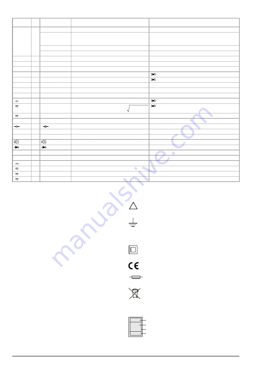
Symbols Used for Rotary Switch Positions
1
Clip = off
3.4
User Interface Symbols in the Following Sections
...
Scroll through main menu
...
Scroll through submenu
Select decimal point,
increase/decrease measuring range
Increase/decrease value
(test voltage for insulation resistance measurement or
threshold for continuity test)
3.5
Symbols on the Instrument
Warning concerning a point of danger
(attention, observe documentation!)
Ground
CAT III / IV
Measuring category III or IV device, see also “Measuring Cat-
egories and their Significance per IEC 61010-1” on page 5
Continuous, doubled or reinforced insulation
Indicates European Conformity
Fuse for current measuring ranges, see chapter 9.3
This device may not be disposed of with the trash. Fur-
ther information regarding the WEEE mark can be
accessed on the Internet at www.gossenmetrawatt.com
under the search term WEEE (see also chapter 9.6).
Calibration seal (blue seal):
See also “Recalibration” on page 53
Switches
FUNC Display
Measuring Function
Additional Current Clamp Sensor Function
Clip = 1:1/10/100/1000
(via the “Setup for currently selected measurement” menu)
RISO
0/4
RISO M
Insulation resistance measurement
Uext
Pulsating voltage, TRMS DC + AC, 15 Hz ... 500 Hz,
only for detection of interference voltage! (before starting
measurement)
Uset
Selectable test voltage: 50, 100, 250, 500 or 1000 V
UISO
Applied/measured test voltage during measurement
Coil
1
Coil L1, L2, L3 [μs]
Short-circuited coil test with optional COIL adapter
Coil
2
DAR [k
/s]
Dielectric absorption rate
Coil
3
PI [k
/s]
>Polarization index
V~
0/5
VAC
Alternating voltage, AC TRMS, full bandwidth
AC clamp (V): Current clamp sensor
Hz
1
Hz
Voltage frequency, full bandwidth
Hz client (V): Current clamp sensor
Hz
2
Duty AC %
Duty cycle measurement
Hz
3
RPM AC
RPM measurement
V~
4
V AC Fil
Alternating voltage, AC TRMS, with low-pass filter (1 kHz)
V
0/3
VDC
1
Direct voltage
DC clamp (V): Current clamp sensor
V
1
V (AC+DC)
1
Pulsating voltage, TRMS
AC + DC clamp (V): Current clamp sensor
V
2
V (AC+DC) Fil
1
Pulsating voltage, TRMS AC DC, with low-pass filter (1 kHz)
0/4
(DC) resistance
1
F
,
nF,
F
Capacitance
Temp. RTD
2
C Pt 100/1000
Temperature with Pt 100 / Pt 1000 resistance thermometer
Temp. TC
3
C, type K
Temperature, type K thermocouple
0/2
Continuity test with acoustic signal
1
V
Diode voltage where I is constant
Rlo
0
R
LO
/2L
2-wire milliohm measurement where I
P
=
/+/- 200 mA
m
/4
0
R
LO
/4W
4-wire milliohm measurement where I
P
= 200 mA or 1 A
A
0/4
ADC
Direct current amperage
A
1
A (AC+DC)
Pulsating current amperage, AC DC TRMS
A
2
AAC
Alternating current amperage, AC TRMS
A
3
Hz
Current frequency
V
ACDC
V
AC
2
V
DC
2
+
=
!
Consecutive number
Registration number
Date of calibration (year – month)
Deutsche Akkreditierungsstelle GmbH – calibration lab
XY123
2019-04
D-K-
15080-01-01


