14
GMC-I Messtechnik GmbH
Operating Overview – Connections, Keys, Rotary Switch, Symbols
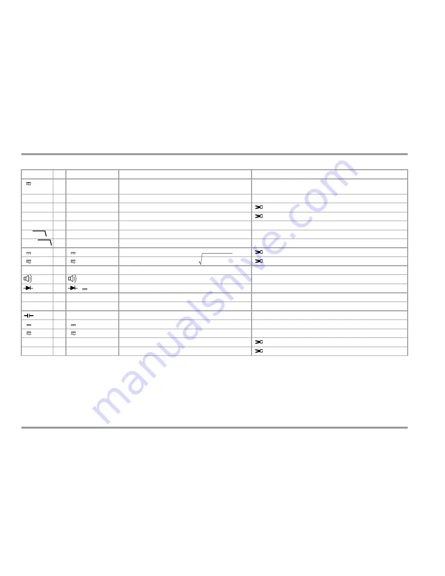
Symbols used for Rotary Switch positions
Switch
FUNC
Display
Measuring Function
Additional Function clip-on (by menu SET
CLIP 1:1/10/100/1000)
V
1M
0/2 V DC AC TRMS
Pulsating voltage, TRMS DC + AC, 15 Hz ... 500 Hz
only for detection of interference voltage!
M
ISO
@UISO
1
UISO / k
M
Insulation resistance measurement
V~
0/5 V~ AC TRMS
Alternating voltage, AC TRMS, full bandwidth
Clip-on AC (V): clip-on current sensor
Hz (V)
1
Hz ~ AC
Voltage frequency, full bandwidth
Clip-on Hz (V): clip-on current sensor
%
2
%
Keying Ratio Measurement (customer-specific variant)
V~
3
V Fil ~ AC TRMS
Voltage frequency, with low pass filter (1 kHz)
Hz (V)
4
Hz Fil ~ AC
Voltage frequency, with low pass filter (1 kHz)
V
0/2 V DC
Direct voltage
Clip-on DC (V): clip-on current sensor
V
1
V DC AC TRMS
Pulsating voltage, TRMS (
)
Clip-on DC + AC (V): clip-on current sensor
0
(DC) resistance
0/2
Continuity test with acoustic signal
1
V DC
Diode voltage where I is constant
Temp RTD
0
C Pt 100/1000
Temperature with Pt 100 / Pt 1000 resistance thermometer
Temp TC
1
C Typ-K
Temperature with thermoelement type K
0
nF,
F
Capacitance
A
0/2 A DC
Direct current value
A
1
A DC AC TRMS
Pulsating current amperage, AC DC TRMS
A~
0/2 A~ AC TRMS
Alternating current amperage, AC TRMS
Clip-on AC (A): clip-on current transformer
Hz (A)
1
Hz ~ AC
Current frequency
Clip-on Hz (A): clip-on current transformer
1kHz
1kHz
ACDC
VAC
2 V
DC
+
=


