background image

GOSSEN METRAWATT GMBH

Contents

......................................................................................................................... Page

1

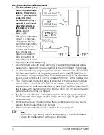
Safety Features and Precautions  ............................................................................5

2

Initial Start-Up  .........................................................................................................7

3

Selecting Measuring Functions and Measuring Ranges  .........................................8

3.1

Automatic Measuring Range Selection  ........................................................................8

3.2

Manual Measuring Range Selection – MAN/AUTO Key  .................................................8

3.3

Quick Measurements .................................................................................................9

4

Display (LCD)  ...........................................................................................................9

4.1

Digital Display  ...........................................................................................................9

4.2

Analog Display  ..........................................................................................................9

5

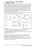
Measured Value Storage – DATA / MIN-MAX Key  .................................................10

5.1

DATA (hold / compare) .............................................................................................10

5.2

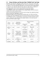
Storage of Minimum and Maximum Values “MIN-MAX” with Time Stamp ....................11

6

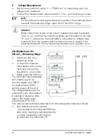
Voltage Measurement  ...........................................................................................12

6.1

Transient Overvoltages .............................................................................................13

6.2

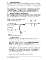
Measuring Voltages of Greater than 300 V  ................................................................13

7

Current Measurement  ...........................................................................................13

7.1

Current Measurement with Current Transformers with Voltage Output  ........................15

8

Resistance Measurement ......................................................................................16

9

Continuity Testing  .................................................................................................16

10

Diode Testing  ........................................................................................................17

11

Capacitance Measurement  ...................................................................................18

12

Frequency Measurement  ......................................................................................18

13

Temperature Measurement with Pt100 and Pt1000  .............................................19

14

Characteristic Values   .........................................................................................20

15

Maintenance .........................................................................................................26

15.1

Batteries .................................................................................................................26

15.2

Fuses ......................................................................................................................26

15.3

Housing ..................................................................................................................27

16

Multimeter Messages  ...........................................................................................27

17

Repair and Replacement Parts Service
DKD Calibration Lab and Rental Instrument Service  .............................................28

18

Product Support  ....................................................................................................28

Summary of Contents for METRAport 32 XS

Page 1: ...METRAport 32 XS Digital Multimeter 3 349 281 02 6 3 04 Operating Instructions ...

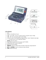
Page 2: ...uring ranges except current measuring ranges 6 connector jack for all measuring ranges 7 OFF ON ON OFF switch 8 Resettable miniature circuit breaker AUTO FUSE 9 Rotary switch for function selection 10 Eyelet for carrying strap 11 MAN AUTO Key for manual and automatic measuring range selection 12 DATA and MIN MAX Key for measured value storage 13 FUNC Multifunction key 3 4 5 6 1 2 7 9 10 12 13 11 8...

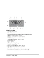
Page 3: ...ction 5 Display memory freeze measured value 6 MIN MAX storage 7 Selected current type DC or AC 8 Unit of measure 9 Over ranging 10 Pointer for analog display 11 Analog display scale 12 Resistance thermometer Pt100 Pt1000 13 Negative analog display range exceeded 14 Zero balancing active 15 Acoustic signal activated e g for continuity testing 1 3 4 7 8 9 10 11 13 14 15 5 6 2 12 ...

Page 4: ...IN MAX with Time Stamp 11 6 Voltage Measurement 12 6 1 Transient Overvoltages 13 6 2 Measuring Voltages of Greater than 300 V 13 7 Current Measurement 13 7 1 Current Measurement with Current Transformers with Voltage Output 15 8 Resistance Measurement 16 9 Continuity Testing 16 10 Diode Testing 17 11 Capacitance Measurement 18 12 Frequency Measurement 18 13 Temperature Measurement with Pt100 and P...

Page 5: ...t anywhere where voltages of greater than 33 V RMS may occur Avoid working alone when taking measurements which involve contact hazards Be certain that a second person is present Maximum allowable voltage between terminals 3 4 5 6 and ground is equal to 300 V category II The current measuring range A is equipped with a magnetic circuit breaker Max allowable voltage at the meas circuit miniature ci...

Page 6: ...cted from the measuring circuit before repair replacement of parts or balancing If repair or balancing of a live open instrument is required this may only be carried out by trained personnel who are familiar with the dangers involved Defects and Extraordinary Strains If it may be assumed that the instrument can no longer be operated safely it must be removed from service and secured against uninte...

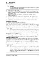
Page 7: ...and leave it there for at least 5 s before returning it to the ON position Note Electrical discharges and high frequency interference may lead to erro neous display values and may disable the measuring sequence Reset the instrument by switching it off and then after 5 s back on again Switching the Instrument Off Manually Set the toggle switch to the OFF position and fold the instrument closed The ...

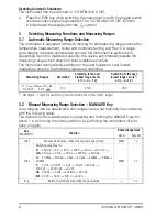
Page 8: ...the following measured quantities 1 28 digits 1 digit for switching from the 300 kHz to the 3 kHz range 3 2 Manual Measuring Range Selection MAN AUTO Key Auto ranging can be deactivated and ranges can be set manually in accordance with the following table The manual mode is deactivated by pressing and holding the MAN AUTO key for about 1 s by turning the rotary switch or by switching the instrumen...

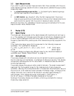
Page 9: ...the jack If the measuring range upper limit is exceeded for the following measured quantities OL overload is displayed V DC I DC Ω Hz V AC I AC 30 nF 3 mF 3099 digits 30 mF 30999 digits The digital display is refreshed at different rates for the individual measured quantities see Display Refresh Rates on page 24 4 2 Analog Display The analog display with simulated pointer and dynamic response equi...

Page 10: ... Reactivation occurs if the indicated measured value limits are fallen short of 2 Double acoustic signal after the first measured value has been stored Thereafter double acoustic signal only occurs if the currently frozen value deviates from the first stored value by less than 10 digits 3 Exception 10 at 300 Ω The DATA function has no effect on the analog display which continues to indicate the cu...

Page 11: ...ally after the function has been activated and stored MIN MAX values and time stamps are deleted in doing so The MIN MAX function is deactivated by pressing and holding the DATA key for about 1 second by turning the function selector switch or by switching the instrument off and back on again Function MIN MAX Key DATA MIN and MAX Measured Values Time Stamps Reaction at Instrument Display Acoustic ...

Page 12: ...t are in danger if the breaking thresholds for the fuses are exceeded due to operator error Zero Balancing in the 300 mV Measuring Range Select the 300 mV measuring range Connect the measure ment cables to the instru ment and connect the free ends to one another Briefly press the FUNC key The instrument acknowledges zero balancing with an acoustic signal and 000 0 1 digit and the ZERO symbol appea...

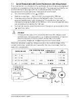
Page 13: ...rve all applicable safety precautions 1 HV3 3 kV 2 HV30 30 kV for DC voltage only 7 Current Measurement First disconnect supply power from the measuring circuit or the power consumer and discharge all capacitors if any are present Select range A with the rotary switch for currents of greater than 300 mA or range mA for currents of less than d 300 mA Always start with measuring range A when measuri...

Page 14: ...protected with a fuse T2 5A 250V in combination with damping diodes The breaking capacity of the slow blow fuse is equal to 10 kA at a nominal voltage of 380 V AC with a resistive load The 15 A current measuring range is protected with a resettable miniature circuit breaker 15A 240V AC 50V DC In order to conform to the CAT requirements an additional slow blowing fuse link T16A 500V has been fit te...

Page 15: ...ng the MAN or the DATA key or the currently selected value can be retained by pressing the FUNC key Connect the clip on current transformer or the clip on current sensor to the and the jacks Attention If the secondary side of the current transformer with voltage output remains open during operation e g if cables are defective or have not been connected or due to a blown device fuse or incorrect co...

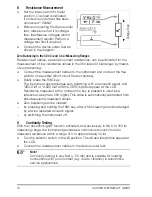
Page 16: ...o balancing with an acoustic signal and 000 0 Ω or 0 000 kΩ and the ZERO symbol appear at the LCD Resistance measured at the moment the key is pressed is used as a reference value max 200 digits This value is automatically subtracted from all subsequently measured values Zero balancing can be cleared by pressing and holding the FUNC key after which clearing is acknowledged by a twice repeated acou...

Page 17: ...instrument As long as voltage drop does not exceed the maximum allowed display value of 1 8 V several elements or reference diodes with minimal reference voltage can be connected in series for testing If 0L appears at the display either the circuit is interrupted or conducting state voltage is greater than 1 8 V Blocking Direction or Interruption 0L is displayed at the instrument If a value of les...

Page 18: ... without a device under test Briefly press the FUNC key The instrument acknowledges zero balancing with an acoustic signal and 00 00 and the ZERO symbol appear at the LCD Capacitance measured at the moment the key is pressed is used as a reference value max 200 digits This value is automatically subtracted from all subsequently measured values Zero balancing can be cleared by pressing and holding ...

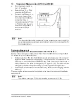
Page 19: ...ensor Cable Resistances from 0 1 Ω to 50 Ω Sensor cable resistances with values other than100 mΩ can be compensated for values of up to 50 Ω as follows Briefly press the FUNC and the MAN AUTO keys simultaneously The currently selected cable resistance is displayed This value can be increased with the DATA key or reduced with the MAN AUTO key Each time one of these keys is briefly activated the val...

Page 20: ...pF Approximate Voltage Drop at MUL A 300 µA 100 nA 160 mV 3 mA 1 µA 160 mV 30 mA 10 µA 200 mV 300 mA 100 µA 300 mV 15 A 10 mA 700 mV Open Circuit Voltage Measuring Current at MUL Ω 300 Ω 100 mΩ 0 6 V max 250 µA 3 kΩ 1 Ω 0 6 V max 45 µA 30 kΩ 10 Ω 0 6 V max 4 5 µA 300 kΩ 100 Ω 0 6 V max 1 5 µA 3 MΩ 1 kΩ 0 6 V max 150 nA 30 MΩ 10 kΩ 0 6 V max 15 nA 300 Ω 0 1 Ω max 3 V max 1 2 mA 3 V 1 1 mV max 3 V m...

Page 21: ...s Overload Capacity 1 rdg d rdg d 2 Value Duration 300 mV 0 5 2 4 0 5 5 7 600 V DC AC eff sine continuous 3 V 0 5 2 0 5 5 30 V 0 5 2 0 5 5 300 V 0 5 2 0 5 5 600 V 0 5 2 0 5 5 600 V CAT I 2 300 µA 0 5 2 0 5 5 0 36 A continuous 3 mA 0 5 2 0 5 5 30 mA 0 5 2 0 5 5 300 mA 0 5 2 0 5 5 15 A 0 5 2 0 75 5 10 A 3 300 Ω 0 5 2 4 300 V DC AC eff sine max 10 s 3 kΩ 0 5 2 4 30 kΩ 0 5 2 300 kΩ 0 5 2 3 MΩ 0 5 2 30...

Page 22: ...ture 0 C 21 C and 25 C 40 C V 0 2 1 V 0 4 1 300 µA 300 mA 0 5 1 3 A 10 A 1 1 300 Ω 300 kΩ 0 2 1 3 MΩ 0 2 1 30 MΩ 1 1 30 nF 30 µF 0 5 1 Hz 0 5 1 C Pt100 0 5 1 Influence Quantity Sphere of Influence max resolution Frequency Intrinsic Error 2 rdg d Frequency V AC 300 0 mV 3 000 V 30 00 V 300 0 V 15 Hz 45 Hz 2 5 65 Hz 1kHz 1 5 Influence Quantity Sphere of Influence max resolution Frequency Intrinsic E...

Page 23: ...r Influence Quantity Sphere of Influence Measuring Range Damping Common Mode Interference Voltage interference quantity max 300 V V 90 dB interference quantity max 300 V 50 Hz 60 Hz sine 300 mV 30 V 60 dB 300 V 60 dB Series Mode Interference Voltage interference quantity V nom value respective measuring range max 300 V 50 Hz 60 Hz sine V 40 dB interference quantity max 300 V nom value respective m...

Page 24: ...ith automatic switching Overload Display triangle appears Sampling Rate 20 measurements per second Digital Display Char Height 7 segment characters 20 mm Number of Places 3 place 3100 steps Overload Display 0L appears Polarity Display is displayed if plus pole is connected to jack Sampling Rate 2 measurements per second Display Refresh Rates V DC V AC A Ω C Pt100 Pt1000 twice per second Hz once pe...

Page 25: ... all current measuring ranges up to 300 mA 15 A range Resettable 15A 240VAC 50VDC miniature circuit breaker additionally a fuse link has been joint in series with the m c b T16A 500VAC 6 3 mm x 32 mm Switching capacity 1 5 kA at 500 V AC and ohmic load Electrical Safety Safety Class II per IEC EN 61010 1 2001 VDE 0411 1 2002 Measurement Category II Operating Voltage 300 V Contamination Level 2 Tes...

Page 26: ...on as possible The instrument requires two 1 5 V batteries in accordance with IEC R 6 or IEC LR 6 Replacing the Batteries Attention Disconnect the instrument from the measuring circuit at all poles before opening the battery compartment Fold the instrument closed Insert a coin or a similar object into the slot between the housing and the battery compartment cover and press down until the battery c...

Page 27: ...A circuit breaker is normal when measuring high value alternating current If the miniature 15 A circuit breaker for the active current measuring range is tripped FUSE appears at the digital display and an acoustic signal is generated simultaneously Make sure that the red pin is popped out in the tripped condition i e that no adhesion or fusion has taken place Short circuit the Ω and 15 A jacks wit...

Page 28: ...presentatives or subsidiaries for service in other countries Calibration Laboratory for Electrical Quantities DKD K 19701 accredited per DIN EN ISO IEC 17025 Accredited measured quantities direct voltage direct current values DC resistance alternating voltage alternating current values AC active power AC apparent power DC power capacitance and frequency 18 Product Support When you need support ple...

Reviews: