14
English
8. Electrical connections
The electrical connections are made to screw terminals
which are easily accessible from the front of the signal
isolator (see Figs. 7 to 10) and can accommodate wire
gauges up to 2.5 mm
2
.
Make sure that the cables are not live when
making the connections!
In the case of
“intrinsically safe”
explosion
proof versions [EEx ib ] IIC or [EEx ia] IIC, the
supplementary information given on the type
examination certification, the EN 60 079-14
and also local regulations applicable to
electrical installations in explosion hazard
areas must be taken into account.
Note that, ...
... the required electrical insulation and
transmission data agree with the data on
the nameplate of the SINEAX TI 807 (
input signals and
output signals)!
... in the case of a signal isolator with
current
outputs 0...20 mA, the total resistance of the
external leads (receiver plus leads)
does
not
exceed the maximum burden of 1000
Ω
(non-Ex version) or 500
Ω
(Ex version)! See
“Output signal” in Section “5. Technical
data”!
... in the case of a signal isolator with
voltage
output 0...10 V, the external receiver
connected across the output has a
sufficiently
high
internal resistance Ri
A
in
relation to the SINEAX TI 807 output
impedance of
500
Ω
! See “Output signal” in
Section “5. Technical data”!
The error due to Ri
A
is:
500 [
Ω
] · 100
Ri
A
[
Ω
]
F [%] =
Signal isolator in housing S17 with
two
isolation
and transmission channels
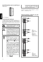
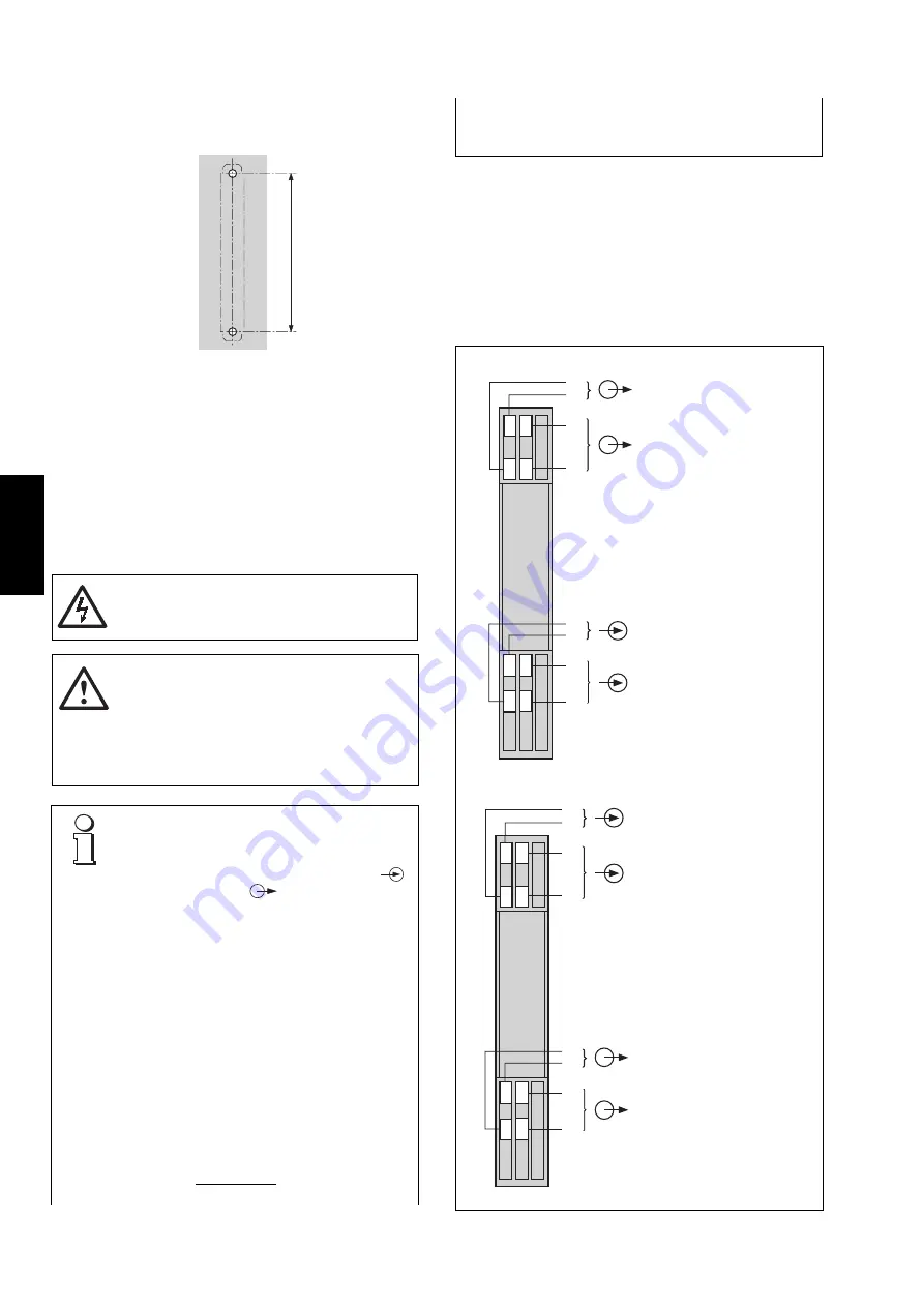
Drill 2 holes in the wall or panel as shown in the drilling pattern
(Fig. 6). Now secure the signal isolator to the wall or panel
using two 4 mm diameter screws.
Fig. 6. Drilling pattern.
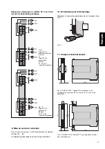
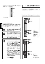
Connect the input and output leads E1 … E3 and A1 … A3
according to Figures 7 to 10.
Fig 7.
Type 807-112…,
standard (non-Ex)
version
and
Type 807-162…,
Ex version
(output signals A1 and
A2 “intrinsically safe”)
Fig. 8.
Type 807-122…,
Ex version
(input signals E1 and
E2 “intrinsically safe”)
1
2
0
1
6
2
7
4
3
9
8
–
+
A1
E1
–
+
A2
+
–
+
+
–
E2
1
6
2
7
4
3
9
8
–
+
A1
E1
–
+
A2
–
+
–
+
+
–
E2
... the input and output cables should be twisted
pairs and run as far as possible away from
heavy current cables!


