15
English
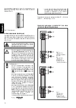
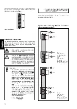
Fig. 13. SINEAX TI 807-1 (housing S17) with the screw hole
mounting brackets pulled out.
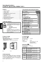
11. Dimensional drawings
Fig. 11
10. Releasing the signal isolator
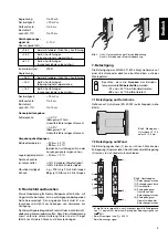
Release the signal isolator from a top-hat rail as shown in
Fig. 11.
9. Commissioning and maintenance
The device is in operation as soon as the input signals
E1 … E3 are connected.
The signal isolator requires no maintenance.
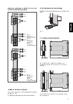
Fig. 9.
Type 807-113…,
standard (non-Ex)
version
and
Type 807-163…,
Ex version
(output signals
A1, A2 and A3
“intrinsically safe”)
Fig. 10.
Type 807-123…,
Ex version
(input signals
E1, E2 and E2
“intrinsically safe”)
Signal isolator in housing S17 with
three
isolation
and transmission channels
Fig. 12. SINEAX TI 807-1 (housing S17) clipped onto a top-hat rail
(35
×
15 mm or 35
×
7.5 mm, acc. to EN 50 022).
1
6
2
7
4
3
9
8
11
12
14
13
–
+
E2
–
+
A3
+
–
+
+
–
E3
–
+
A1
A2
+
–
E1
1
6
2
7
4
3
9
8
11
12
14
13
–
+
E2
–
+
A3
+
–
+
+
–
E3
–
+
A1
A2
+
–
E1
146.5
17.5
120
+0.5
+
0
145.5
120
134
120
Ø
4.5
6.5
12
14
17.5
+0,5
+
0


