18 GMC-I Messtechnik GmbH
7.
Inputs/Outputs
7.1.
Note Regarding All Measuring Channels
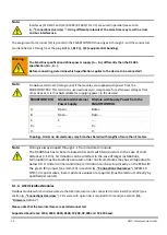
Note:
The following points must be observed in order to achieve high measuring accuracy:
Use shielded cables only. If possible, connect the shield to a separate ground contact
(available as a shield bus with the SMARTCONTROL/IP65).
Large cable diameters, at least 0.6 mm (recommended: 0.8 mm, max. 1.5 mm)
Keep cables as short as possible.
Ferrite beads attached to both cable ends
Do not lay cables parallel to heavy current conductors!
7.2.
Analog Inputs (current/voltage)
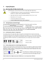
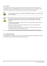
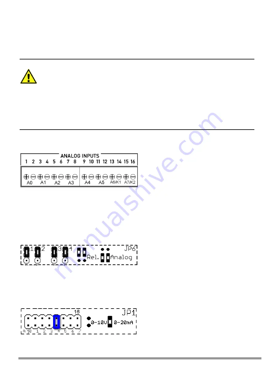
The connector plugs are designated, and must be connected, as shown below (polarity as specified):
+ =
Measuring signal
- =
All eight inputs have a common ground
which also functions as the negative terminal.
They are not electrically isolated.
7.2.1.
Selecting Relay Outputs / Analog Inputs
The 6 analog inputs, A0 through A5 (terminals 1 through 12), are intended for the connection of measuring
transducers (e.g. pressure sensor, atmospheric humidity sensor etc.) with 0 to 10 V or 0 to 20 mA output signals.
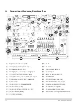
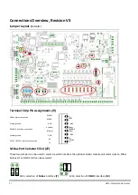
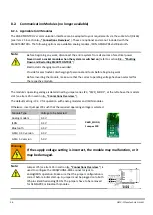
Terminals 13 through 16 can be used either as relay outputs K1 and K2 or analog inputs A6 and A7. Jumper series
JP6 determines whether a relay output or an analog input will be used. The relay output mode is the default
value.
Series 1+2: A6/K1
Series 3+4: A7/K2
7.2.2.
Setting Analog Inputs to Current/Voltage Measurement
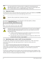
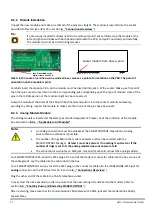
Voltage or current measurement is selected with jumper series JP1. These jumpers are assigned to the respective
analog input (from left to right: A0 to A7), and are set to the voltage measurement operating mode (0 to 10 V) at
the factory. In order to measure a current signal (0 to 20 mA), the blue jumper which corresponds to the analog
input must be inserted as follows:
This example shows a voltage measurement at A0-A3 and
A5. A4 us used as a current measuring input. With this layout
for the JP6 series, A6 and A7 are relay outputs K1 and K2.
Internal resistance for voltage measurement: 200 kOhm, for current measurement: 249 Ohm

