20 GMC-I Messtechnik GmbH
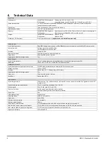
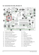
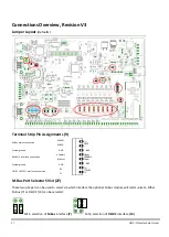
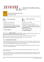
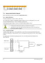
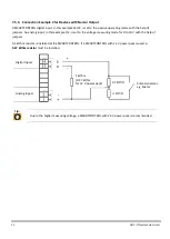
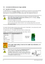
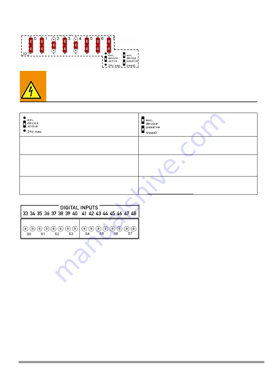
This example shows the configuration for 6 passive
digital inputs (S0, S1, S3 and S5-S7) and 2 active inputs
(S2 and S4).
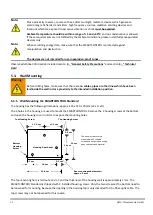
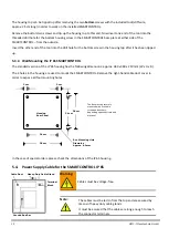
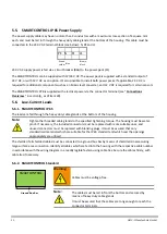
Warning:
Polarity is determined by the jumper setting.
Polarity must be correct!
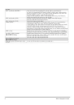
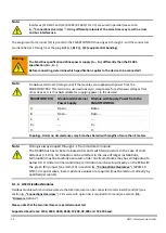
“Active” jumper setting
“Passive” jumper setting
Terminal a = pulse input /
Terminal b = pulse input / status –
Terminal a = contact - / GND
Terminal b = c / open collector
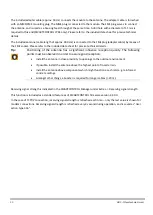
Connection of, for example, pulse generators with
their own 12 to 24 V power supply / output signal
with load capacity of at least 15 mA
Connection of, for example, pulse generators with
reed contact and a minimum contact / open collector
load capacity of 15m A
** Electrical isolation **
GND connected to each other
** No electrical isolation **
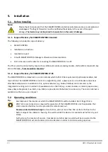
Sample terminal assignments (S2 and S4 active , rest
passive):
S0a GND, S0b + (as well as S1, S3, S5-S7)
S2a +, S2b – (as well as S4)
7.4.2.
Configuring the Digital Inputs
If a digital input is used as a status input (e.g. door contact, burner on-time etc.), a status command must be set
up with SMARTCONTROL Manager software in order to assure that every change to the input signal is recorded
[see section entitled SMARTCONTROL Manager, Status Command Type].
These tariff and synchronizing inputs are configured with SMARTCONTROL Manager software (see the “Meters”
section in the SMARTCONTROL manual.
It’s also possible to record tariff data, for example peak tariff (HT) and off-peak tariff (NT). There are 3 tariff
inputs: IS1, IS3 and IS5.
A 0 or 1 signal applied there (floating relay, peak/off-peak tariff signal) specifies whether assigned inputs IS0, IS2
and IS4 will be counted as peak or off-peak tariff. For example, tariff input IS1 specifies whether pulses from IS0
will be allocated to HT or NT.

