33 GMC-I Messtechnik GmbH
9.2.2.
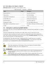
Status Display / Error Diagnosis – DIAG LED
DIAG LED description: Brief blinking: . (dot), long blink: - (dash)
Pause: short pause: _ , long pause: __ (underline)
Mode
Pattern
Description
Normal operation:
- _ - _ - _ -
Long blink, short pause
General error:
. . . . . . . . .
Fast, short blinking
Onboard flash (2 MB) defective:
.- __ .-__ .-
Short, long and long pause
Compact flash error:
.. __ .. __ ..
Short, short and long pause
Password deleted:
-. __ -. __
Long, short, long pause
Deleting flash memory:
................
Very short blinking (flickering)
Maintenance mode (as of firmware version
1.1.34):
._.__._. __._.
Short blink, short pause, short blink and long
pause
9.3.
Shutting Down and Restarting SMARTCONTROL
Approximately once every 15 minutes, SMARTCONTROL transfers recorded data from volatile RAM to non-volatile
flash memory.
Data stored in RAM which have not yet been written to flash memory are lost in the event of a restart.
A maintenance mode is provided as of firmware version 1.1.34, allowing for immediate saving of data before a
restart. After pressing and holding the F1 key [see item 14 in section 6. , “Connections Overview,”] for 5 seconds,
data are written from RAM to non-volatile flash memory.
The blinking pattern at the DIAG LED changes. The SMARTCONTROL can now be shut down or restarted by
pressing the reset key [see item 15 in section 6. , “Connections Overview,”]. If no further action is taken after
pressing the F1 key, the SMARTCONTROL resumes normal operation after 60 seconds.
Tip:
Information regarding the current firmware version can be displayed in the SMARTCONTROL
Manager by accessing “Info” in the “Configuration” tab.
9.4.
Configuration
Note:
In order to start data recording, the SMARTCONTROL must be configured with SMARTCONTROL
Manager software.
SMARTCONTROL must therefore be connected to the PC for initial configuration. This connection
can be established by means of the Ethernet port or one of the socket modem options.

