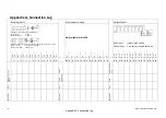
Appendix A, Connection Log
Appendix A, Connection Log
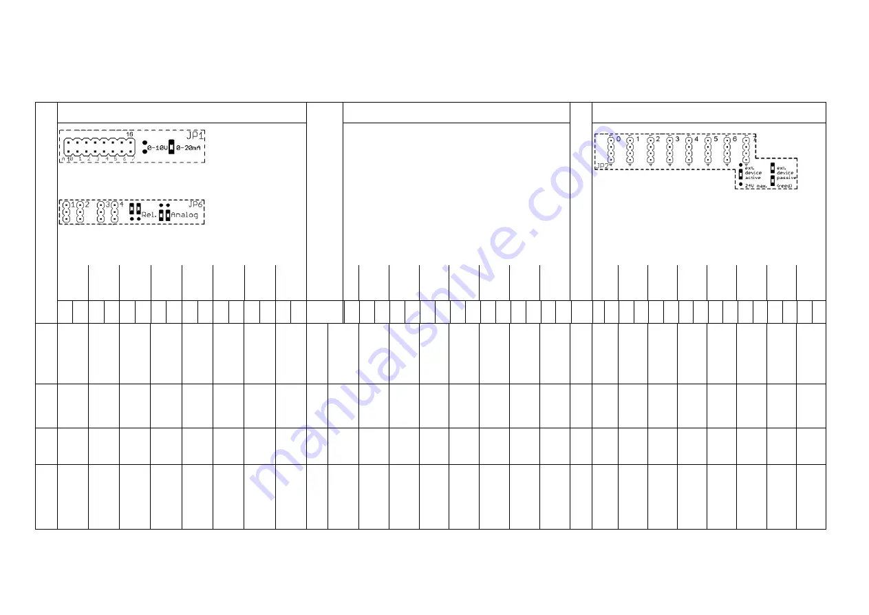
8 analog inputs
8 temperature inputs
8 digital inputs
Setting for current/voltage measurement
With jumper:
0 - 10 V
Without jumper:
0 - 20 mA
A6/A7 as analog inputs or relay outputs K1/K2 (series 1+2 A6, 3+4 A7)
Jumper at top:
relay (default setting)
Jumper at bottom:
analog input
Only suitable for Pt 1000
Active input:
jumper in the middle
Passive input:
2 jumpers occupy the entire row
+A0
-
A0
+A1
-
A1
+A2
-
A2
+A3
-
A3
+A4
-
A4
+A5
-A5
+A6
-
A6
+A7
-
A7
T0
T1
T2
T3
T4
T5
T6
T7
a I
S0
b I
S0
a I
S1
b I
S1
a I
S2
b I
S2
a I
S3
b I
S3
a I
S4
b I
S4
a I
S5
b I
S5
a I
S6
b I
S6
a I
S7
b I
S7
1
2
3
4
5
6
7
8
9
10
11
12
13
14
15
16
17
18
19
20
21
22
23
24
25
26
27
28
29
30
31
32
33
34
35
36
37
38
39
40
41
42
43
44
45
46
47
48
Unit
Off
set
M
et
er
/c
o
n
ve
rt
er
fa
ct
o
r
Measu
ri
ng
ran
ge
C
ab
le
le
ng
th
/
d
ia
.
Type
Wire
Wire
Wire
Desig
na
ti
on
Desig
na
ti
on
Desig
na
ti
on
A
GMC-I Messtechnik GmbH

