All Rights reserved, No Spreading without GOSUNCN Permission
18
Hardware Development Guide
ME3616
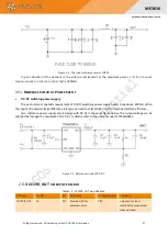
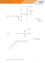
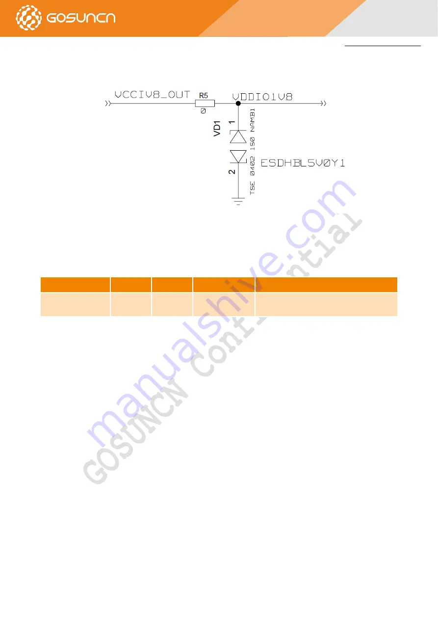
The test circuit is shown in the figure below. It is recommended to add electrostatic protection near the VCC1V8_OUT
module pin.
Figure 2-5 VCC1V8_OUT reference design
2.7.
P
OWER ON SCENARIO
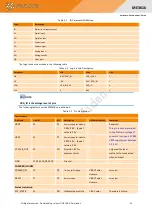
The table below is the information of power-on/off pin
Table 2-6 Definition of POWER_ON
Pin Name
Pin NO.
I/O
Description
Comment
POWER_ON
19
DI
Turn on/off the
module
low active., the voltage level is VBAT, Please pay
attention to level matching
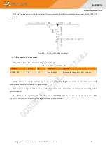
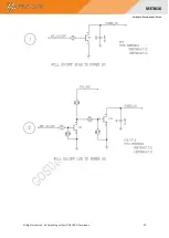
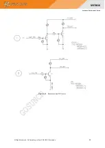
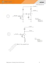
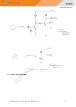
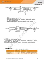
When MCU can provide high/low level pulse with adjustable length, the reference circuit to turn-on/off
module is as shown in the following figure below.
The resistors in Figures below are only the recommended value and they need to adjust according to the
actual situation.
1.
Power-on by dynatron, the circuit
①
connect ON/OFF to high level to power-on the module, the
circuit
②
can connect ON/OFF to low level to power-on the module

