Components and Operation
English, Revision 03, Date: 07.02.2012
13
Programming A Transponder Using The Profibus Internface
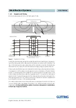
For the positioning of the transponder to the reading antenna q. v. Figure 10 on page
21. The bits DATA and CD will be set after the transponder has entered the antenna
field. As the reading range exceeds the programming range, the programming should
be implemented not before the crossing of the antenna’s centre (positioning bit is set
for 100 ms), if DATA and CD are reset after the blanking interval.
Programming will be initiated by a rising edge of the PROG bit; i.e. first the transponder
code which has to be programmed with PROG=0 should be transferred, subsequently
the same transponder code wit PROG=1. So the released programming process lasts
approx. 100 ms. Afterwards the new code will be read directly and is available for the
input bytes.
2.2.6
Profibus Address
2 Hex- rotary switches under 2 blind plugs are available for the adjustment of the pro-
fibus address (q. v. Figure 4 on page 8). Set the address in area 0 to 7E with a screw-
driver and seal the plugs accordingly. A readjusted address will only be accepted after
the antenna has been turned- off and -on again.
2.2.7
RS 232 - Interface
Here the transmission parameters are fixed: 38400, 8 data bit, even parity, continuous
output, ASCII- coded. Transponders can be programmed via the serial interface (see
section 4.2 on page 20).
If a transponder code is read the following data will be put out (using a 5ms pattern)
after having connected the supply voltage.
-
16 Bit transpondercode as a decimal number between 0..65535
-
Status of LED
CD
-
Staus of LED
DATA
-
Status of LED
POS
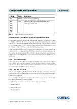
Priority
Name
Significance
0x01
PROG
Transponder programming
0x02
CLR
Internal deletion of the last transponder code
0x04
0x08
0x10
0x20
0x40
0x80
Currently not allocated
Table 12
Significance of the instruction bit


