background image

5

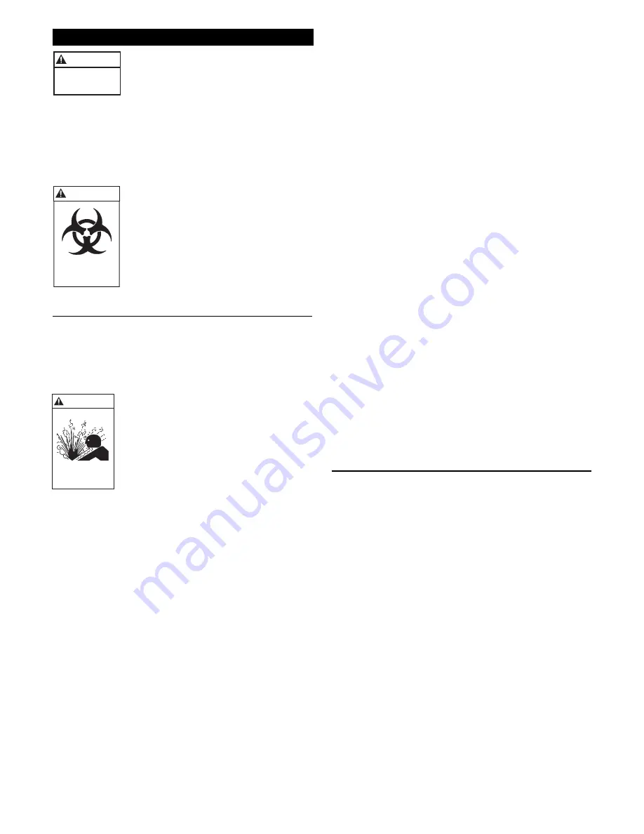
WARNING

Biohazard can 
cause serious 
personal injury.

5. Remove and discard the mechanical seal and stationary

seat assembly. DO NOT damage the motor shaft or the
stationary seat bore.

6. Inspect and wipe clean the stationary seat bore.

7. To install the new stationary seat into the seal housing,

lubricate the stationary seat bore and motor shaft with
clean motor insulating oil. Using Goulds mechanical seal
installation tool (A02A013), slide the stationary seat
fully and squarely into the seal housing.

8. With a clean, lint free cloth, wipe the stationary face

clean of all lubricating oil or debris. DO NOT scratch or
otherwise damage the seal face.

9. Lubricate the inside of the rotary elastomer with clean

motor insulating oil. Using the Goulds installation tool,
slide the seal rotary assembly onto the motor shaft and
seat fully against the stationary seat. Remove the seal
installation tool.

10. Install the impeller onto the motor shaft by turning the

impeller on CLOCKWISE, tighten securely. Treat the
impeller with Loctite™ #271 and securely install. When
provided, securely install the impeller locknut.

11. Fill the motor cover with motor special insulating oil to

within

 1

2

" (13 mm) of the seal chamber housing. Tape

drain plug with Teflon™ tape and install plug securely.

12. Reassemble casing and new casing gasket to pump

assembly by installing the four casing hex cap screws,
torquing in sequence to 35 lbs ft (47 

Ν

 m).

NOTICE: FOLLOW THE INSTRUCTIONS PROVIDED

IN THE “WIRING AND GROUNDING” AND
“OPERATION” SECTIONS OF THE
MANUAL AFTER UNIT DISASSEMBLY,
REASSEMBLY.

POWER CABLE REPLACEMENT

1. To gain access to the motor cover screws follow steps 1

through 6 in the “MECHANICAL SEAL
REPLACEMENT
” section of this manual.

2. Remove the power cable strain relief (484B) assembly

from the motor cover and slide up the cable.

3. Remove the four bearing housing socket head screws

(371C). Carefully slide the motor cover from the motor
assembly. DO NOT damage the power cable.

4. Disconnect the power cable wires from the motor

assembly (338).

5. Remove cable from motor cover, inspect and replace as

required, following the procedures provided.

NOTICE: DISCARD STRAIN RELIEF ASSEMBLY.

THEY CAN NOT BE REUSED.

6. Install new motor cable strain relief assembly onto cable,

sliding the hex gland on first, then the washer and finally
the packing. Insert the cables into the motor cover hole.
Pull an appropriate amount of cable through the motor
cover to allow for connecting the cable leads. DO NOT
tighten the strain relief gland.

WARNING

Hazardous
voltage

Disassembly/Assembly

FAILURE TO DISCONNECT AND
LOCKOUT ELECTRICAL POWER
BEFORE ATTEMPTING ANY
MAINTENANCE CAN CAUSE
SHOCK, BURNS OR DEATH.

NOTICE: FOLLOW ALL SAFETY AND LIFTING

INSTRUCTIONS PROVIDED IN THIS
MANUAL.

• Following the slide rail instructions, remove the pumping

unit from the sewage containment area.

UNIT MUST BE FLUSHED AND
DISINFECTED, INSIDE AND OUT,
PRIOR TO SERVICING.

MECHANICAL SEAL REPLACEMENT

1. Follow ALL instructions provided in the

“DISASSEMBLY” section of this manual.

2. To gain access to the pump impeller and mechanical seal

remove the four casing hex cap screws (372D). Remove
casing (100) and casing gasket (351); discard the gasket.

FAILURE TO REMOVE DRAIN
PLUG CAREFULLY CAN CAUSE
HOT OIL TO ERUPT FROM OIL
RESERVOIR CAUSING PERSONAL
INJURY OR PROPERTY DAMAGE

3. Removal of the mechanical seal assembly (387) requires

draining the special insulating oil from the motor cover.
This is accomplished by removing the drain plug and
draining the oil into an adequately sized clean receptacle.
See “ENGINEERING DATA” section for required
volume.

4. To remove the impeller (101), it may be necessary to

heat the impeller and impeller locknut (304), three phase
motors only, with a torch. Use no more heat that is
necessary, as excess heat will damage the mechanical
seal. Secure the impeller from rotation, and remove
the impeller lock nut, by turning the lock nut
COUNTERCLOCKWISE. Remove the impeller
from the motor shaft by holding the motor shaft with a
screw driver and turning the impeller COUNTER-
CLOCKWISE.

Hazardous pressure can
cause personal injury or
property damage.

CAUTION

Summary of Contents for 3885

Page 1: ...4 Disassembly Assembly 5 Mechanical Seal Replacement 5 Power Cable Replacement 5 Start Capacitor Replacement 6 Motor Replacement 6 Engineering Data 7 Sectional Assembly 8 Repair Parts and Materials of Construction 9 10 Typical 2 Slide Rail Installation 11 Typical Plumbing and Installation 11 Trouble Shooting 12 Goulds Pumps Limited Warranty 12 Owner s Information Model Number Serial Number Dealer ...

Page 2: ...applications and 2 50 mm solids for sewage applications in the discharge pipe to prevent backflow Follow the check valve manufacturer s installation instructions Install an adequately sized gate valve ABOVE the check valve for pump plumbing and check valve maintenance To deter air locking drill a3 16 4 8 mm hole 2 50 8 mm beyond the pump discharge connection All piping must be adequately supported...

Page 3: ... for tamper resistant operation Standard and heavy duty steel or aluminum doors are available The pit access door must be of sufficient size to allow for inspection maintenance and crane or hoist service Liquid Level Controls Single float operation can be used on1 3 and1 2 HP models Mounting of the float switch must be checked by the installer to insure proper turn on and turn off The pump may be ...

Page 4: ...nd correctly crimped Sta Kon or equivalent connectors Insulate and water proof each joint using heat shrink tubing equipped with a self contained sealer Apply heat evenly from a torch until adequately sealed OR Use plastic insulators and a neoprene gasket sleeve set with properly sized and correctly crimped Sta Kon connectors Place a cap and gasket on each wire end center insulator body over splic...

Page 5: ...e 4 Disconnect the power cable wires from the motor assembly 338 5 Remove cable from motor cover inspect and replace as required following the procedures provided NOTICE DISCARD STRAIN RELIEF ASSEMBLY THEY CAN NOT BE REUSED 6 Install new motor cable strain relief assembly onto cable sliding the hex gland on first then the washer and finally the packing Insert the cables into the motor cover hole P...

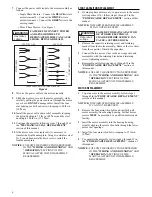
Page 6: ...y follow steps 6 through 12 in the POWER CABLE REPLACEMENT section of this manual NOTICE FOLLOW THE INSTRUCTIONS PROVIDED IN THE WIRING AND GROUNDING AND OPERATION SECTIONS OF THE MANUAL AFTER UNIT DISASSEMBLY REASSEMBLY WARNING Hazardous voltage 7 Connect the power cable leads to the motor assembly as follows Single Phase Motors Connect the BLACK wire to motor terminal L1 Connect the WHITE wire t...

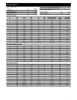
Page 7: ...0 3 60 9 2 4 6 K 2 87 11 46 14 4 15 10 2 3450 230 1 60 18 0 F M 1 1 S 2 2 14 3 20 2 3450 200 230 460 3 60 12 0 11 6 5 8 K 1 66 6 62 14 4 15 10 ELECTRICAL DATA 3886 AND 3887BF 1 3 1725 115 1 60 9 8 M 1 92 16 3 15 1 3 1725 230 1 60 4 9 N 7 58 16 3 10 1 2 1725 115 1 60 14 5 N 1 6 16 3 20 1 2 1725 230 1 60 7 3 K 6 4 16 3 10 1 2 1725 200 3 60 3 8 K 6 55 14 4 10 1 2 1725 230 460 3 60 3 3 1 7 K 9 9 39 4 ...

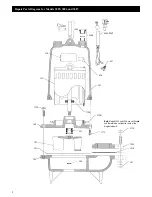
Page 8: ... Models 3885 3886 and 3887 456 GROUP 457 376 338 372D 340 112A 412M 371C 371H 195C 351A 357 304 387 101 351 100 436 341 Note Models 3885 and 3886 are not flanged and therefore do not require some of the diagramed parts 484B 458 ...

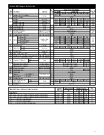
Page 9: ...32 4K384 112B Upper Ball Bearing Steel 1 4K132 4K432 5 gallons 1 2 gallons 304 Impeller Locknut 3 PH only AISI 300 series SS 1 13K6 1 Phase 115V 118 121R 118 1222R N A N A N A N A 338 Motor 1 Phase 230V 118 122R 118 1223R 118 1232R 118 1233R 118 1334R 120 845R 3 Phase 230 460 V N A 118 1321R 118 1322R 118 1323R 118 1324R 120 8425R 3 Phase 200 V N A 118 1333R 118 1334R 118 1335R 118 1336R 120 8425R...

Page 10: ... 6K76 1 5 Discharge Flange 3 NPT OPT Cast Iron 1 A1 3 1 5 Motor Insulating Oil Approx 1 Gallon Required 304 Impeller Locknut 3 PH only AISI 300 series SS 1 13K6 Motor 1 Phase 115V 118 121R 118 123R N A N A N A N A N A Motor 1 Phase 230V 118 122R 118 124R 118 1212R118 1213R118 1233R 120 844R 120 845R 338 Motor 3 Phase 230 460 V Stainless Steel 1 N A 118 132R 118 1304R 118 134R 118 1323R N A N A Mot...

Page 11: ...L GROUT SEAL HIGH LEVEL ALARM OPTIONAL FLOAT SWITCH ALARM LIGHT OPTIONAL HINGED ACCESS DOOR WRENCH OPERATED VALVE VENT VALVE OPERATING ROD DISCHARGE CHECK VALVE SLIDE RAIL GUIDE 3 MIN SUBMERGENCE MAINTENANCE ONLY 6 NORMAL OPERATION INFLUENT INFLUENT ALARM LIGHT OPTIONAL HINGED ACCESS DOOR WRENCH OPERATED VALVE VENT VALVE OPERATING ROD DISCHARGE CONTROL PANEL SERVICE POLE CHECK VALVE SLIDE RAIL GUI...

Page 12: ...listed in the DESCRIPTION AND SPECIFICATIONS section impeller is locked motor bearings or shaft is damaged Clear debris from casing and impeller consult with dealer a Manual operation Power cable is damaged Resistance between power leads must read as shown in ENGINEERING DATA Resistance between power leads and ground should read infinity If any reading is incorrect call a qualified electrician b A...

Page 13: ...e 17 Reemplazo del sello mecánico 17 Reemplazo del cable de alimentación 17 Reemplazo del condensador de arranque 18 Reemplazo del motor 18 Datos de ingeniería 19 Montaje seccional 20 Partes de repuesto y materiales de construcción 21 22 Instalación típica de riel corredizo de 2 pulg 23 Plomería e instalación típica 23 Identificación y resolución de problemas 24 Garantía limitada de Goulds Pumps 2...

Page 14: ... efluentes y sólidos de 2 pulgadas 50 mm para aplicaciones de aguas negras en la tubería de descarga para evitar el contraflujo Siga las instrucciones de instalación del fabricante de la válvula de retención Instale una válvula de compuerta de tamaño adecuado SOBRE la válvula de retención para el mantenimiento de la bomba la plomería y la válvula de retención Para evitar la obturación por aire per...

Page 15: ...evantamiento y un dispositivo de traba para permitir una operación resistente a las manipulaciones indebidas Se ofrecen puertas de acero o aluminio estándar o reforzado La puerta de acceso a la fosa debe ser de tamaño suficiente para permitir la inspección y el mantenimiento y para el servicio de grúa o montacargas Controles del nivel de líquido En los modelos de 1 3 y 1 2 HP puede utilizarse una ...

Page 16: ...s procedimientos Una a tope los alambres con conectores Sta Kon o equivalentes del tamaño adecuado y correctamente plegados Aísle e impermeabilice cada junta con tubo de contracción por calor con un sellador autocontenido Aplique calor en forma uniforme con un soplete hasta sellar adecuadamente O Utilice aisladores plásticos y una camisa de empaquetadura de neopreno con conectores Sta Kon de tamañ...

Page 17: ...AS EN LAS SECCIONES DE ALAMBRADO Y CONEXIÓN A TIERRA Y OPERACIÓN DEL MANUAL DESPUÉS DE DESMONTAR O REENSAMBLAR LA UNIDAD REEMPLAZO DEL CABLE DE ALIMENTACIÓN 1 Para tener acceso a los tornillos de la cubierta del motor siga los pasos 1 a 6 en la sección de REEMPLAZO DEL SELLO MECÁNICO de este manual 2 Retire el protector contra tirones 484B del cable de alimentación de la tapa del motor y deslice e...

Page 18: ...ES DE ALAMBRADO Y CONEXIÓN A TIERRA Y OPERACIÓN DEL MANUAL DESPUÉS DE DESMONTAR O REENSAMBLAR LA UNIDAD ADVERTENCIA Tensión Peligrosa 5 Retire el cable de la cubierta del motor inspecciónelo y reemplácelo según sea requerido siguiendo los procedimientos suministrados AVISO DESECHE EL PROTECTOR CONTRA TIRONES YA QUE NO PUEDE VOLVER A USARSE 6 Instale un nuevo protector contra tirones en el cable de...

Page 19: ... 3 20 11 2 3450 200 3 60 10 6 K 1 9 14 4 15 11 2 3450 230 460 3 60 9 2 4 6 K 2 87 11 46 14 4 15 10 2 3450 230 1 60 18 0 F M 1 1 S 2 2 14 3 15 10 2 3450 200 230 460 3 60 12 0 11 6 5 8 K 1 66 6 62 14 4 15 10 DATOS ELÉCTRICOS 3886 Y 3887 1 3 1725 115 1 60 9 8 M 1 92 16 3 15 1 3 1725 230 1 60 4 9 N 7 58 16 3 10 1 2 1725 115 1 60 14 5 N 1 6 16 3 20 1 2 1725 230 1 60 7 3 K 6 4 16 3 10 1 2 1725 200 3 60 ...

Page 20: ...os 3885 3886 y 3887 GRUPO 456 457 376 338 372D 340 112A 412M 371C 371H 195C 351A 357 304 387 101 351 100 436 341 Nota los Modelos 3885 y 3886 no son bridados y por lo tanto no requieren algunas de las partes incluidas en el diagrama 484B 458 ...

Page 21: ... A N A N A N A 338 Motor monofásico 230V 118 122R 118 1223R 118 1232R 118 1233R 118 1334R 120 845R trifásico 230 460 V N A 118 1321R 118 1322R 118 1323R 118 1324R 120 8425R trifásico 200 V N A 118 1333R 118 1334R 118 1335R 118 1336R 120 8425R 340 Caja del cojinete Hierro fundido 1 1K167 1K332 10 0 341 1 PH Hierro fundido 1 1K207 1K207 1K208 1K208 1K208 1K208 23 0 3 PH 1K208 351 Empaquetadura de la...

Page 22: ... N A N A N A Motor monofásico 230 V 118 122R 118 124R 118 1212R118 1213R 118 1233R 120 844R 120 845R 338 Motor trifásico 230 460 V Acero inoxidable 1 N A 118 132R 118 1304R 118 134R 118 1323R N A N A Motor trifásico 200 V N A 118 1314R118 1316R118 1316R 118 1335R N A N A Motor trifásico 200 230 460 V N A N A N A N A N A 120 8425R120 8425R 340 Caja del cojinete Hierro fundido 1 1K167 1K332 10 0 Cub...

Page 23: ...DE FLOTADOR LUZ INDICADORA DE ALARMA OPCIONAL PUERTA DE ACCESO ABISAGRADA VÁLVULA OPERADA CON LLAVE ORIFICIO DE VENTILACIÓN VARILLA DE OPERACIÓN DE LA VÁLVULA DESCARGA VÁLVULA DE RETENCIÓN GUÍA DEL RIEL CORREDIZO INMERSIÓN MÍN DE 3 PULG MANTENIMIENTO ÚNICAMENTE OPERACIÓN NORMAL DE 6 PULG AFLUENTE AFLUENTE VÁLVULA OPERADA CON LLAVE ORIFICIO DE VENTILACIÓN VARILLA DE OPERACIÓN DE LA VÁLVULA DESCARGA...

Page 24: ... con aire Consulte la acción recomendada arriba El impulsor está gastado o dañado Inspeccione el impulsor reemplácelo si así se requiere Los controles de nivel de líquido están Inspeccione reajuste o reemplace según sea requerido defectuosos o posicionados incorrectamente La válvula de retención de descarga no funciona Inspeccione repare o reemplace según sea requerido El área de contención de agu...

Page 25: ...29 Remplacement de la garniture joint mécanique 29 Remplacement du câble d alimentation 29 Remplacement du condensateur de démarrage 30 Remplacement du moteur 30 Données techniques 31 Dessin en coupe modèles 3885 3886 et 3887 32 Pièces de rechange et matériaux modèles 3885 3886 et 3887 33 34 Système à rail de guidage type de 2 po 35 Installations types 35 Diagnostic des anomalies 36 Garantie limit...

Page 26: ... non retour laissant passer les solides de 19 mm 3 4 po ou de 50 mm 2 po selon qu il s agit d une pompe à effluents ou à eaux d égout Suivre les directives du fabricant du clapet pour l installation Installer EN AVAL après du clapet de non retour un robinet vanne de calibre approprié permettant l entretien de la pompe de la tuyauterie et du clapet Afin de prévenir les poches d air percer un trou d...

Page 27: ... poignée de levage et d un verrou intraficable Elles sont offertes en aluminium ou en acier pour un service ordinaire ou dur Les trappes doivent être assez grandes pour permettre l inspection et l entretien de la pompe ainsi que l emploi d un dispositif de levage Régulateurs de niveau Un régulateur de niveau à simple contacteur à flotteur peut servir pour les pompes de 1 3 et 1 2 hp L installateur...

Page 28: ...à bout au moyen de connecteurs Sta KonMC ou l équivalent sertis correctement et de grosseur appropriée Isoler et étancher chaque connexion avec une gaine thermorétrécissable contenant un produit d étanchéité Chauffer la gaine uniformément avec un chalumeau jusqu à ce que la connexion soit bien étanche OU Utiliser des isolants en plastique et un manchon d étanchéité en néoprène ainsi que des connec...

Page 29: ... le changer au besoin selon les directives fournies AVIS JETER LE PRESSE GARNITURE DU CÂBLE CAR ON NE PEUT LE RÉUTILISER 6 Poser un presse garniture neuf au câble d alimentation en plaçant d abord le fouloir à tête hexagonale puis la rondelle et la garniture Insérer le câble dans son orifice sur l enveloppe Faire pénétrer dans l enveloppe la longueur de câble nécessaire à la connexion des fils NE ...

Page 30: ... le condensateur de démarrage moteurs monophasés suivre les étapes 1 à 5 de la section précédente REMPLACEMENT DU CÂBLE D ALIMENTATION AVIS JETER LE PRESSE GARNITURE DU CÂBLE D ALIMENTATION CAR ON NE PEUT LE RÉUTILISER OMETTRE DE DÉCHARGER LE CONDENSATEUR AVANT D EFFECTUER L ENTRETIEN PEUT CAUSER UN CHOC ÉLECTRIQUE GRAVE 2 Déposer la vis et la ferrure de fixation du condensateur au moteur Déconnec...

Page 31: ...3 450 230 460 3 60 9 2 4 6 K 2 87 11 46 14 4 15 10 2 3 450 230 1 60 18 0 F M 1 1 S 2 2 14 3 20 2 3 450 200 230 460 3 60 12 0 11 6 5 8 K 1 66 6 62 14 4 15 10 DONNÉES ÉLECTRIQUES 3886 ET 3887 1 3 1 725 115 1 60 9 8 M 1 92 16 3 15 1 3 1 725 230 1 60 4 9 N 7 58 16 3 10 1 2 1 725 115 1 60 14 5 N 1 6 16 3 20 1 2 1 725 230 1 60 7 3 K 6 4 16 3 10 1 2 1 725 200 3 60 3 8 K 6 55 14 4 10 1 2 1 725 230 460 3 6...

Page 32: ...3885 3886 et 3887 456 457 376 338 372D 340 112A 412M 371C 371H 195C 351A 357 304 387 101 351 100 436 341 Nota Les modèles 3885 et 3886 ne comportent pas de bride et ne requièrent donc pas certaines des pièces illustrées 484B 458 ...

Page 33: ...1222R s o s o s o s o 338 Moteur 1 PH 230 V 118 122R 118 1223R 118 1232R 118 1233R 118 1334R 120 845R 3 PH 230 460 V s o 118 1321R 118 1322R 118 1323R 118 1324R 120 8425R 3 PH 200 V s o 118 1333R 118 1334R 118 1335R 118 1336R 120 8425R 340 Logement de roulement Fonte 1 1K167 1K332 10 0 341 1 PH Fonte 1 1K207 1K207 1K208 1K208 1K208 1K208 23 0 3 PH 1K208 351 Joint d étanchéité corps de pompe Compos...

Page 34: ...o s o s o Moteur 1 PH 230 V 118 122R 118 124R 118 1212R118 1213R 118 1233R 120 844R 120 845R 338 Moteur 3 PH 230 460 V Inox 1 s o 118 132R 118 1304R 118 134R 118 1323R s o s o Moteur 3 PH 200 V s o 118 1314R118 1316R118 1316R 118 1335R s o s o Moteur 3 PH 200 230 460 V s o s o s o s o s o 120 8425R120 8425R 340 Logement de roulement Fonte 1 1K167 1K332 10 0 Enveloppe de moteur 1 PH 1K207 1K207 1K2...

Page 35: ...EUR VOYANT D ALARME EN OPTION TRAPPE DE VISITE À CHARNIÈRE ÉVENT TIGE DE MANOEUVRE DU ROBINET REFOULEMENT CLAPET DE NON RETOUR GUIDE DE RAIL IMMERSION MIN 3 po POUR ENTRETIEN SEULEMENT VARIATION 6 po CYCLE NORMAL INFLUENT INFLUENT VOYANT D ALARME EN OPTION TRAPPE DE VISITE À CHARNIÈRE ÉVENT REFOULEMENT TABLEAU DE COMMANDE POTEAU D AMENÉE DE COURANT GUIDE DE RAIL JOINT DE COULIS ALARME NIVEAU HAUT ...

Page 36: ...ectricien Poche d air dans la pompe Voir le correctif recommandé pertinent ci dessus Roue usée ou endommagée Inspecter la roue et la remplacer au besoin Régulateurs de niveau défectueux Inspecter régler ou remplacer les régulateurs au besoin ou mal placés CYCLE DE FONCTIONNEMENT Clapet de non retour du tuyau Inspecter réparer ou remplacer le clapet au besoin RÉPÉTÉ SANS ARRÊT de refoulement défect...

Reviews: