50.04.504 / 1.0
Copyright by GOVI GmbH 2021. The reproduction of this document or any part thereof is prohibited. We reserve the right to make technical changes during the course of further developments.
OPERATION MANUAL - Trailer Refrigeration Unit
arktik 1600N • 1600 N/T • 2000N • 2500N • 2000P • 2500 N/K • 2000 P/K
33
Page
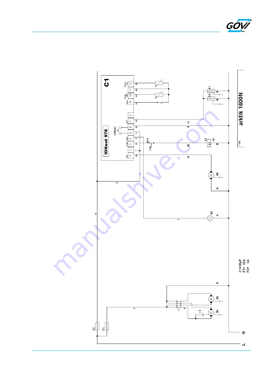
Fig. 13-2 Wiring Diagrams
13.2 Wiring Diagrams
The wiring diagram is placed inside the main cover of the trailer
refrigeration unit.
Legend of the wiring diagram
F1
Main fuse
F2
Control switch
M1
Compressor motor
M2
Condenser fan motor
M3
Evaporator fan motor
E1
Defrosting
E2
Sump heating
E3
Drain heater
K1
Relay compressor
HP1
Pressure control (HP)
HP2
Pressure switch condenser fan
C1
Temperature controller
Pb2
«Defrost» sensor
Pb1
«Room temperature» sensor
S1
«Interior lighting» switch
S2
«On/off» switch
H1
Interior lighting
Door
Door contact switch
K2
Contactor heat
K3
Contactor evaporator fan
TR
Transformer
R4
Roomheater
R5
Roomheater
2R1
Defrosting
2R2
Sump heating
2R3
Drain pipe heater
T
Overheatprotector
IC974LX
Temperature controller


