11
GETTING
ST
ARTED
SAFETY
/
SPECIFICA
TIONS
OPERA
TION
MAINTENANCE
/
REP
AIR
TROUBLESHOOTING
ASSEMBL
Y /
INST
ALLA
TION
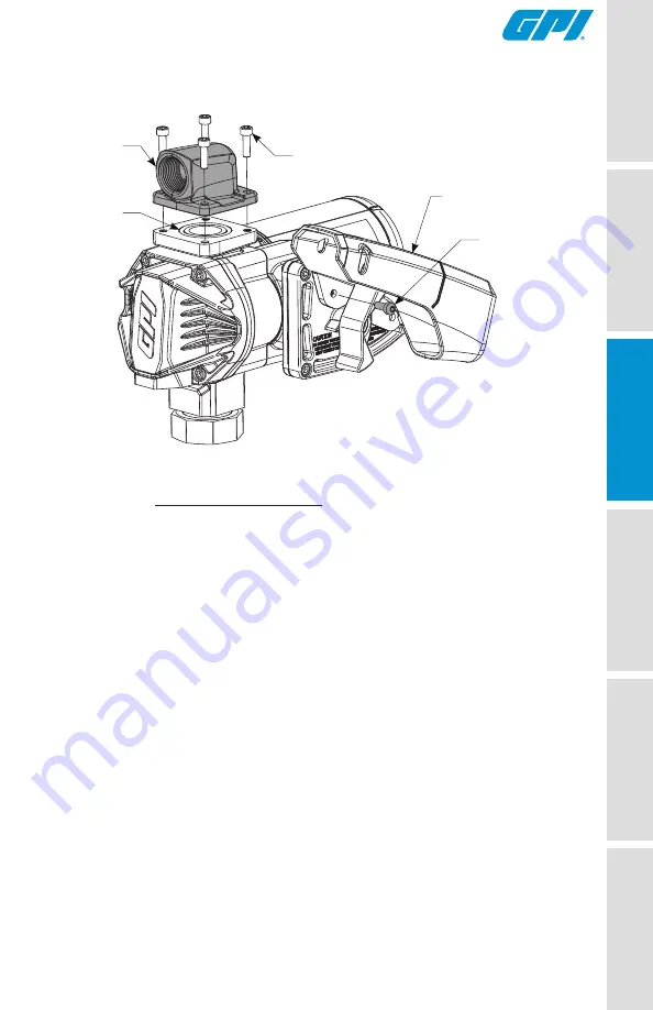
Figure 5
INSTALLATION INSTRUCTIONS (CONTINUED)
Install Hose and Nozzle
1. Wrap one end of the dispensing hose with three to four turns of thread
tape and thread into outlet port. Tighten securely using an adjustable
wrench.
2. Wrap opposite end of hose with three or four turns of thread tape
and thread into nozzle. Tighten securely using an adjustable wrench.
3. Place the nozzle into the nozzle holder on the end of the pump motor
housing. Note that the nozzle cannot be placed in the holder unless
the pump switch is OFF (see Figure 9).
Outlet
Adapter
M6-1.0 x 20mm
SHCS
M6-1.0 x 14mm
BHCS
Nozzle Cover
#222
O-ring


