background image

12

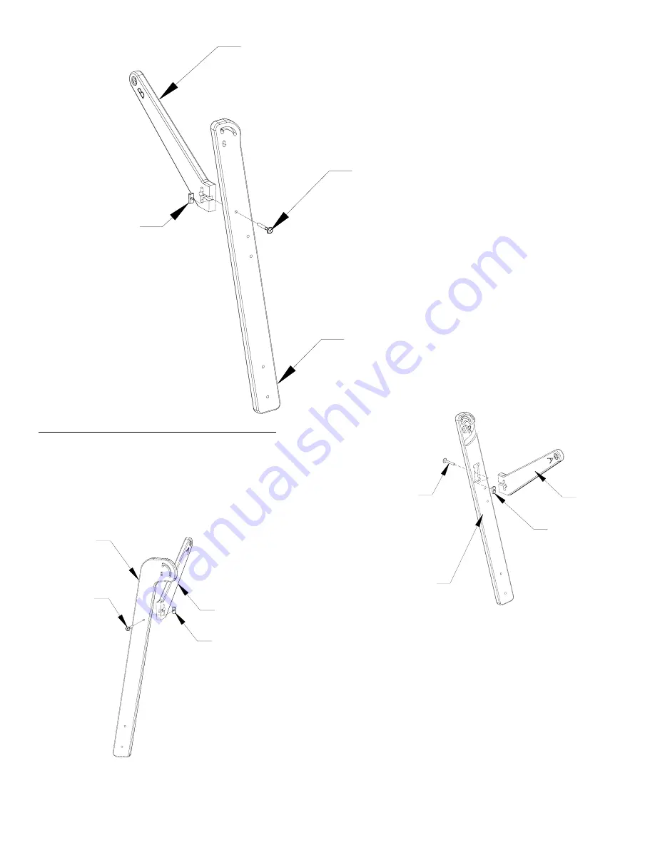
Side Leg

Front Right

Side Leg

Brace "A"

1/4" Rectangle Nut

1/4" X 45mm

Connector Bolt

Side Leg

Brace "B"

Side Leg Front Left

1/4" X 45mm

Connector Bolt

1/4" Rectangle Nut

Side Leg

Back Left

Side Leg

Brace "A"

1/4" X 45mm

Connector Bolt

1/4" Rectangle Nut

•  Place a rectangle nut vertically in the “t” slot of the Side Leg 

Brace “A”, as illustrated to the left.


•  Connnect the Right Front Side Leg to the Side Leg Brace 

“A” by threading the connector bolt through the hole in the 

Right Front Side Leg and into the rectagle nut. (Holding the 

rectagle nut in place, while using the provided allen wrench to 

tighten the connector bolts.)

•  Complete the above steps again to complete the Left Back 

Side Leg.

Step 7:  Side Leg Brace “A” Assembly

Parts Needed:  2- 

Side Leg Brace “A”


1- Right Front Side Leg


1- Left Back Side Leg


2- 1/4” X 45mm Connector Bolt


2- 1/4” Rectangle Nut (threaded)

Front Left Side Leg 

Outside View

•  Complete the above steps again to complete the 

Left Front Side Leg.

Front Right Side Leg

Inside View

Back Left Side Leg

Outside View

Summary of Contents for Little Gracie II

Page 1: ... 18 Cross Brace Assembly 20 Step 19 Cone Thread Holder Assembly 20 Step 20 Cone Thread Guide Assembly 21 Step 21 Lever to Carriage Assembly 21 Step 22 Lever Linkage to Handle Assembly 22 Step 23 Pedal Clamp to Handle Assembly 24 Step 24 Carriage to Frame Assembly 24 Step 25 Sewing Machine to Frame Assembly 25 Step 26 Stylus Clamp Base Assembly 25 Step 27 Stylus Clamp Assembly 25 Step 28 Stylus Ass...

Page 2: ...ght Take Up Rail Mount End 1 Left Take Up Rail Mount End 1 Left Fabric Layers Rail Mount End 1 Right Fabric Layers Rail Mount End 1 Table 1 1 Table 2 1 Table 3 2 Carriage Stop Base 2 Carriage Stop Clamp 1 Left Front Leg 1 Right Front Leg 1 Right Back Leg 1 Left Back Leg 2 Middle Leg A 2 Middle Leg B 3 Cone Thread Disk ...

Page 3: ...ack Support 1 Back Queen Table Aluminum Track Support 1 Front Queen Table Aluminum Track Support 3 Fabrifast Tubing 4 Bungee Clamp 2 Middle Leg Spacer 2 Track Support Splice 1 Right Back Lever 1 Front Lever 1 Back Lever Linkage 1 Front Lever Linkage 1 Middle Lever 1 Pedal Clamp 1 Left Back Lever 1 Pedal Clamp Wheel 3 Pedal Clamp Spacer 2 65 1 2 Plastic Track 2 99 1 2 Plastic Track 3 Rail Coupler 3...

Page 4: ... X 7 8 Screw 67 3 16 Flat Washer 27 1 4 Flat Washer 22 1 1 4 Fender Washer 23 1 4 Plastic Knob 20 1 4 Nylock Nut 57 1 4 Jam Nut 12 1 4 Rectangle Nut 4 1 4 X 30mm Connector Bolt 4 1 4 X 3 Carriage Bolt 2 10 X 3 Eye Bolt 1 1 4 X 2 Eye Bolt 4 10 Hex Nut 1 4mm Allen Wrench 2 1 4 X 2 1 4 Carriage Bolt 13 1 4 X 35 mm Connector Bolt 2 1 4 X 40 mm Connector Bolt 1 Fabri fast Tool 12 10 X 3 8 Socket Head S...

Page 5: ...turned only with a valid RMA which may be obtained by calling GraceWood Inc at 1 800 264 0644 or 1 801 485 6688 NOTE Warranty card must be filled out stamped and mailed to the address on the card within 30 days of purchase Contact Information For Technical Support or any other correspondence concerning your Little Gracie call 1 800 264 0644 OR E mail robin graceframe com OR Fax 801 908 8888 OR Wri...

Page 6: ...r message and we will promptly ship any item needed 4 For your convenience an L and R have been etched into the INSIDES of most pieces to help you distinguish between left and right parts and inside and outside of parts 5 Identify Hardware Packets All hardware is separated by type and each packet is labeled for ease in identification you will find packets located in a rectangular box 6 This is a n...

Page 7: ...n the Left Take Up Rail Mount End making sure the head of the bolt is on the side with the L Left Take Up Rail Mount End Inside View Right Take Up Rail Mount End Inside View HINT Some holes in the wood pieces may be a little tight for the hardware If this is case tap in the hardware using the handle of your screw driver Place one washer and one jam nut on the end of the bolt TIGHTEN JAM NUTS COMPL...

Page 8: ...Flat Washer 4 1 4 X 1 1 2 Carriage Bolt Right Fabric Layers Rail Mount End Inside View Left Fabric Layers Rail Mount End Inside View Place one of the carriage bolts through each of the holes on the Left Fabric Layer Rail Mount End making sure the head of the bolt is on the side with the L Place one washer and one jam nut on the end of the bolt IMPORTANT Completely tighten the jamb nut onto the bol...

Page 9: ...t Washer As shown in the drawing place the bolts in the Right Take Up Rail Mount End through the first slot on the Right Rail Mount End Place a fender washer followed by a plastic knob on the top bolt Put a washer and then a nylock nut on the bottom bolt NOTE Leave all the nylock nuts loose to allow the washer to turn in your fingers Follow the above steps for the Left Take Up Rail Mount End Right...

Page 10: ...sher 12 1 4 Jam Nuts Right Frame End Outside View Left Frame End Outside View Place one of the carriage bolts through each of the holes except for the two on each end on the Right Frame End making sure the head of the bolt is on the side with the R Place one washer and one jam nut on the end of the bolt REMINDER Completely tighten the jamb nut onto the bolt until the head of the bolt is pulled int...

Page 11: ...s Needed 2 Side Leg Brace B 1 Right Back Side Leg 1 Left Front Side Leg 2 1 4 X 45mm Connector Bolt 2 1 4 Rectangle Nut threaded Place a rectangle nut vertically in the t slot of the Side Leg Brace B as illustrated to the right Follow the above steps again to complete the left side The nylon side of the nylock nut faces out when threading it on the bolt NOTE Leave all the nylock nuts loose enough ...

Page 12: ... by threading the connector bolt through the hole in the Right Front Side Leg and into the rectagle nut Holding the rectagle nut in place while using the provided allen wrench to tighten the connector bolts Complete the above steps again to complete the Left Back Side Leg Step 7 Side Leg Brace A Assembly Parts Needed 2 Side Leg Brace A 1 Right Front Side Leg 1 Left Back Side Leg 2 1 4 X 45mm Conne...

Page 13: ...in the joint and loose enough to allow the washer to turn in your fingers Right Frame End Outside View Put the Right Front Side Leg on the pre installed bolts on the Right Frame End below the Fabric Layer Rail Mount End Place a fender washer on the top bolt and then thread and tighten the plastic knob onto the bolt Place the flat washer on the bottom bolt and then tighten the nylock nut Make sure ...

Page 14: ...track support to the Table 2 Follow the above steps to attach the back crib table aluminum track support to the Table 1 and 2 Place the Table 3 on the front queen table aluminum track support as pictured left Step 9 Table Assembly Parts Needed 1 Table 1 1 Table 2 1 Table 3 1 Front Crib and Queen Table Aluminum Track Support 1 Back Crib and Queen Table Aluminum Track Support 12 or 18 1 4 X 3 4 Phil...

Page 15: ...ck support as show above and to the left Put a phillips pan head screw through the left hole following the same steps as you did for the right Follow the above steps to attach the Middle Leg Spacer to the back crib table aluminum track support Place your Crib Table 2 next to you Queen Table 3 Where your Crib Table meets your Queen table you will place a Table Splice flat end against the aluminum t...

Page 16: ... Left Frame End 1 Table crib or queen 8 1 4 X 1 Phillips Pan Head Screw 4 1 4 X 3 4 Phillips Pan Head Screw Place your Left Frame End on the left side of your table Table 1 It is recommended that you prop the right side of the table on something so you can put the left side on first The two holes on the back of your Left Frame End is where the 1 4 X 1 phillips pan head screw go through to screw in...

Page 17: ...o what you just did on the back Follow the above instructions to attach your Right Frame End to your table except the Left Frame End can hold up your table Step 13 Middle Leg Installation Parts Needed 1 or 2 Middle Leg assembled 2 or 4 1 4 Plastic Knob 2 or 4 1 1 4 Fender Washer 2 or 4 1 4 Nylock Nut 2 or 4 1 4 Flat Washer Queen Assembly ONLY Lay the Little Graice on it s side with the front down ...

Page 18: ...On the other bolt you will put a fender washer and then a plastic knob You will have to push the A Side down enough to get it on the bolts on the back side of your frame The right side is just opposite of the above instructions The illustration on the previous page will help Step 14 Middle Leg Assembly Parts Needed 1 or 2 A Middle Leg 1 or 2 B Middle Leg 1 or 2 Middle Leg Brace 2 or 4 1 4 X 45mm C...

Page 19: ... Nuts Queen ONLY Next insert a 10 socket head screw through the hole in the rail and into the square nut of the end cap Follow the above instructions to put the rest of the square end caps on the 64 Rails If you are setting up your frame in crib you will put a round end cap on the other end in the same manner as above First you will install one square end cap on the end of each 64 Rail Place the s...

Page 20: ...on the 64 Rail First insert one end of the coupler into the end of the rail Insert a 10 socket head screw through the second hole from the end of the rail and into the threaded hole of the coupler Tighten this screw all the way Repeat this step for the other end of the coupler connecting it to the 34 rail Note the direction in which the teeth arc on the ratchet wheel in the picture on the followin...

Page 21: ...Then force the end cap on the opposite side of the frame into the hole on the right rail mount end You will have to flex the side of the frame out a little to accomplish this Repeat this process for all three rails Reference the picture to the left for rail and ratchet wheel position When all the rails are in place put an end cap shoulder on the end of each end cap with a 7 8 screw ...

Page 22: ...r two the rachet stop goes to the right of the ratchet wheel Step 18 Carriage Handle Assembly Parts Needed 1 Top Carriage preassembled 1 Right and Left Handle 4 1 4 X 30 mm Connector Bolt 4 1 4 Jamb Nut Put a connector bolt through both holes on the bottom of your Left Handle Base and through your Top Carriage Under your Top Carriage is where you will put the jam nut on your connector bolt It is e...

Page 23: ...chine install the regular foot pedal platform according to the original text of the instruction booklet OPTION 1 THINNER PLATFORM If using a speed control mechanism to power you machine as opposed to the machine s foot pedal install the new thinner platform shown below NOTE This is a new item not listed in the parts list It is installed using the same hardware and same procedure as the regular foo...

Page 24: ...ole if you are looking at it from the back The eye of the bolt must be right over the Cone Thread Holder as soon as you have it in the correct place you will want to loosen the jamb nut so it is right against the handles Place a washer on the end of the bolt and follow it with a jamb nut You will follow the above instructions for the other bolt except you must have the second bolt even with the fi...

Page 25: ...to turn in your fingers On your Right or Back Lever you will place a bolt which has 1 4 washer on the end through the hole on the longer side as shown on the previous page On the end of the bolt sticking out of your Back Lever you will place a 1 4 washer and then slide the bolt through the hole on the back of your Handle Place a 3 16 washer on the end of the bolt and then screw a nylock nut on the...

Page 26: ...er Linkage On the end of the bolt sticking out of your Back Lever Linkage you will place a 1 4 washer and then slide the bolt through the middle hole on your Middle Lever Place a 3 16 washer on the end of the bolt and then screw a nylock nut on the end Make sure nylock nuts are loose enough to allow the washer to turn in your fingers On the end of a 35mm connector bolt you will want to put a 1 4 w...

Page 27: ... 1 4 Nylock Nut 1 1 1 4 Fender Washer 1 1 4 Plastic Knob Slide the 1 4 x 3 carriage bolt through the top hole on your Middle Lever On the end of the bolt you will want to slide 2 Pedal Clamp Spacers with the more hollow side towards the head of the bolt On the end of the bolt you will now want to put a 3 16 washer followed by a jamb nut which needs to be TIGHTENED COMPLETELY on the bolt Then place...

Page 28: ...n be made by doing the following Loosen the nuts on the outside of the carriage as labeled in the picture On the inside of the carriage turn the screw using a Phillips head screw driver If the track is off centered toward the outside of the carriage adjust the screw so that the wheel moves closer to the edge of the carriage If the track is off centered toward the inside of the carriage adjust the ...

Page 29: ...nt Place a fender washer and then screw a knob on each of the bolts Step 29 Stylus Assembly Parts Needed 1 Stylus Clamp Base assembled 1 Wooden Stylus 1 1 1 4 Fender Washer 1 1 4 Plastic Knobs 1 1 4 X 2 Eye Bolt You will place the eye bolt up through the bottom or the hollow side as pictured right On the end of the bolt you will place a washer and then tighten the knob onto the bolt Before you tig...

Page 30: ... 2 1 4 Jam Nut 2 1 1 4 Fender Washer 2 1 4 Plastick Knob You will be building two carriage stops but one at a time Take the carriage bolt and place it through the Carriage Stop Base The end of the carriage bolt you will need to put a flat washer followed by a jamb nut TIGHTEN the jam nut completely on the bolt and make sure the top of the bolt is flush against the wood Once you have the jam nut on...

Page 31: ...illustrated to the right Follow the above instruction for the left side Take your rail and place it in between the 4th Rail Brackets with the square plastic cap on the left side and the round plastic cap on the right side as shown left Place a plastic end cap in the hole on the outside of the Left Frame End You will then screw the plastic end cap to the square plastic cap Place a plastic end cap i...

Page 32: ...As you cut your fabric layers we recommend making the quilt backing about 6 8 longer and 2 4 wider than your top This will allow for a little give in the backing especially if using thicker batts LITTLE GRACIE FABRIC INSTALLATION The recommended method for installing fabric onto the rails is to make and use Cloth Leaders instructions to follow This will enable you to finish your quilt completely t...

Page 33: ...t into the slot If you wish to do this create a casing on one end of each leader by folding over the fabric one inch 1 and using your foot pedal as a guide stitching the fabric together 3 4 from the fold This will leave about of fabric beyond the stitching Leave the edges open on both ends You may then slide your tubing into the casing Mark each cloth leader at the center length wise Mark or baste...

Page 34: ...ake up rail cloth leader Pin along the solid line you made earlier As you pin allow the quilt to lay natural Avoid pulling or stretching the fabric STEP 2 QUILT TOP TO THIRD RAIL Determine which will be the front and back edges of your quilt Line up the center of your fabric layer with the center of the cloth leader on the 3rd Rail Pin the back edge of your top to the leader cloth This is to be do...

Page 35: ...e same line as your backing is a smooth manner STEP 5 PUTTING YOUR MACHINE CARRIAGES ONTO FRAME First remove your Cone Thread Holder off your carriage before you can slide your machine inside You may have to take your cone thread guides out Remove the take up rail with fabric and rest it on the bottom of the rail mount ends Slide your machine into the carriage from the back It might be easier if y...

Page 36: ... 2nd and 3rd rails allowing them to roll freely Then with one or both hands roll the 1st rail forward rolling the completed work area onto that rail TIP As you roll forward the quilt will accumulate on the 1st rail Be sure to raise the Pole Mount Ends slightly as needed so that the bottom of the rolled up fabric stays about 1 8 above the thoat place of the sewing machine base Failing to do so will...

Reviews: