background image

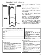
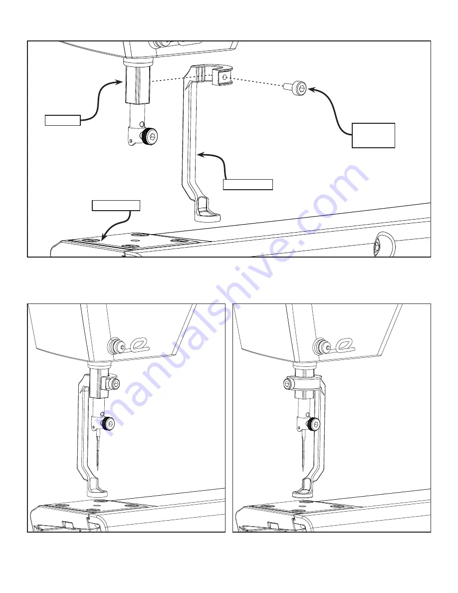
4.  Place 4 sheets of paper under the foot and lower the hopping foot to the top of the surface. You 

may need to use 2 sheets more or less of paper if your project is particularly thick or thin.

5.  Tighten the bolt using the 3mm Allen Wrench.

Note: 

The Hopping foot can be positioned in either of the positions shown.

Make sure not to overtighten the Hopping Foot to prevent binding the Press Bar.

35

|

Maintenance

Hopping Foot

Needle Plate

Hopping Foot

Press Bar

M3 Thumb 

Screw

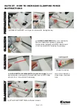
Summary of Contents for Q'nique

Page 1: ...Copyright January 1 2017 Jim M Bagley GraceWood Inc Reproduction Prohibited Version 1 21in Sewing Machine ...

Page 2: ...ssembly 7 Encoder Cables 9 Threading The Sewing Machine 11 Winding The Bobbin 15 Installing The Bobbin Case 17 Adjusting Thread Tension 18 Plugging In The Cables 19 Final Checklist 20 Sewing Basic Controls 21 Main Menu 22 Sewing Modes 23 Tools Menu 25 Maintenance Replacing The Encoder Spring 29 Needle Plate 30 Hook Holder 31 Timing The Machine 32 Hopping Foot 34 Thread Tension 36 Changing the Need...

Page 3: ...Appendix Needle Information ix Thread Information x Additional Tips xi ii Table of Table of Contents ...

Page 4: ...le causing it to break v Switch the sewing machine off when making any adjustments in the needle area such as threading needle changing needle threading bobbin or changing presser foot etc vi Always unplug sewing machine from the electrical outlet when removing covers lubricating or when making any other user servicing adjustments mentioned in the instruction manual Connect this machine to a prope...

Page 5: ...r replacement of the cord or plug is necessary do not connect the equipment grounding conductor to a live terminal Check with a qualified electrician or serviceman if the grounding instructions are not completely understood or if in doubt as to whether the product is properly grounded Do not modify the plug provided with the product if it will not fit the outlet have a proper outlet installed by a...

Page 6: ...mum Stitches Per Minute 90 8 Input Voltage 110 220 VAC 9 Peak Power Consumption 300 W 10 Timing Belt System 11 Bobbin Type Large M Class 12 OLED Screen 13 Custom Ergonomic Handles and Handlebars for efficiency and extended use 14 Built in Bobbin Winder 15 Dual Thread Tension Guides for precise tension v Technical Data Specifications Front Right Left Rear ...

Page 7: ...n Sensor 7 Dual Thread Tension Guide 8 Small Thread Tensioner 9 Large Thread Tensioner 10 Thread Guides 11 Take Up Lever 12 Lamp 13 Needle Bar 14 Needle 15 Hopping Foot 16 Thread Stand 17 Carriage wheels 18 Hand wheel 19 Bobbin Case vi Technical Data Feature Overview 19 10 1 3 11 6 13 4 15 9 5 7 12 18 2 16 8 14 17 16 ...

Page 8: ...st Assembly OLED Screen with Cable Rear Wheel Assembly Front Wheel Assembly Plastic Base Right Lint Brush Bobbin Case Long Encoder Cable Needle 10 Timing Spacer Short Encoder Cable Lower Encoder Black Spring Bobbin 3 one in bag M6 x 20mm SBHCS 2 M6 x 10mm SBHCS 6 vii Technical Data Parts Tools ...

Page 9: ...handle Allen Wrench 2 5mm T handle Allen Wrench 2mm T handle Allen Wrench Flat Head Screw Driver M6 x 16mm Shoulder Bolt 2 Upper Encoder Spring Silver M3 Thumb Screw Needle Screw M3 Hopping Foot Screw Lower Encoder Spring Black viii Technical Data Parts Tools ...

Page 10: ... Needed Front Wheel Assembly Rear Wheel Assembly 4mm T Handle Allen Wrench M6 x 20mm 2 1 Attach the Front Wheel Assembly to the sewing machine using two M6 x 16mm Shoulder Bolts 2 Attach the Rear Wheel Assembly using two M6 x 20mm SBHCS M6 x 16mm Shoulder Bolt 2 1 Setup Assembly Wheel Assembly ...

Page 11: ...e and secure it in place with the M6 x 16mm FCHS screws Handle Assembly 3 Insert the handle cables into the plugs Make sure the cable connectors are plugged in so that the Green Stickers are facing up 4mm T Handle Allen Wrench 2 Setup Assembly Handle Assembly M6 x 16 FCHS Screw Handle Cover Plate M6 x 16 FCHS Screw Handle Cover Plate Handle Assembly Handle Cable Connectors Connector Leads ...

Page 12: ... until they are at a comfortable angle then retighten the set screw 2 Loosen the Clamp Assembly and rotate the handle until it is in the desired position then retighten the Clamp Assembly 3 Repeat step 2 for the other handle 3 Setup Assembly Handle Adjustment M8 Set Screw Clamp Assembly ...

Page 13: ...place then plug the Display Cable Connector into the Display Cable Port M6 x 10mm SBHCS 2 Thread Mast Assembly OLED Display and Cable 4mm T Handle Allen Wrench 3 Attach the Thread Mast Assembly by screwing it to the side of the machine using two M6 x 10mm SBHCS 4 Setup Assembly Display Thread Mast Setup OLED Display Display Cable Connector M6 x 10mm SBHCS Thread Mast Assembly Twist the Cable 180 D...

Page 14: ...dle Allen Wrench 2 Loosen the set screws on the Wheel Supports and adjust them by sliding them to the proper spacing to fit the top carriage then retighten the set screws 5 Setup Assembly Carriage Adjustment Wheel Support Set Screw Bottom Carriage Wheel Support Wheel Support Wheel Support Set Screw ...

Page 15: ...e Left M6 x 10mm SBHCS 4 4mm T Handle Allen Wrench 1 Attach the Plastic Base to the end of the Wheel Assemblies using M6 x 10mm SBHCS 2 Repeat the same process for the other side 6 Setup Assembly Plastic Base Assembly M6 x 10mm SBHCS Left Plastic Base ...

Page 16: ... necessary parts and that the lock collar is loose 4mm T Handle Allen Wrench Upper Encoder Silver Spring Lower Encoder Black Spring 2mm T Handle Allen Wrench Parts Tools Needed 7 Setup Assembly Encoder Assembly Shoulder Spacer Washer Wheel Spacer Plastic Stop M6 x 16mm SBHCS Wheel Lock Collar Front Right Left Rear The encoders must be installed in the left rear position of the top and bottom carri...

Page 17: ...rriage 6 Twist the lock collar on the Lower Encoder to the left and tighten the set screw using the 2mm Allen wrench to tension the encoder Lower Encoder Black Spring Lower Encoder Black Spring Upper Encoder Silver Spring Upper Encoder Silver Spring 8 Section Title Subtitle Setup Assembly Encoder Assembly Upper Encoder Silver Spring Wheel Lower Encoder Black Spring Wheel Twist Lock Collar to the R...

Page 18: ...t Encoder Cable into the Upper Encoder The tab on the cables plug should face away from the encoder 9 Section Title Subtitle Setup Assembly Encoder Cables Encoder Encoder Foot Pedal Quilt Motion Control USB Connector Port Short Encoder Cable Upper Encoder Silver Spring ...

Page 19: ...Make sure all cables are firmly plugged in 2 Plug the Long Encoder Cable into the Lower Encoder The tab on the cables plug should face away from the encoder 10 Section Title Subtitle Setup Assembly Encoder Cables Long Encoder Cable Encoder Port Encoder Cables Lower Encoder Black Spring ...

Page 20: ... Scarf Eye Point Shaft Shank Front View Side View Groove 3 Dual Thread Tension Guide 1 Thread Cone and Thread Stand 2 Thread Mast 4 Small Thread Tensioner 5 Thread Guide 9 Thread Guide 7 Thread Guide 6 Large Thread Tensioner 8 Take Up Bar 11 Eye of the Needle 10 Needle Bar Eyelet ...

Page 21: ...t the thread through the top hole on the dual thread tension guide wrap the thread around and through the bottom hole of thread guide 1 Place thread on the cone style thread stand 12 Section Title Subtitle Setup Assembly Threading The Sewing Machine Dual Thread Tension Guide Thread Cone Thread Stand Small Thread Tensioner Thread Mast ...

Page 22: ...ng 8 Pull the thread through the hole in the take up lever 7 Loop the Thread around the thread guide below the large thread tensioner 5 Feed the thread through the thread guide above the large thread tensioner 13 Setup Assembly Threading The Sewing Machine Check Spring Thread Guide Thread Guide Take Up Lever Large Thread Tensioner ...

Page 23: ... through the bottom thread guide 10 Feed the thread through the eyelet in the front of the needle bar 11 Feed the thread through the eye of the needle 14 Setup Assembly Threading The Sewing Machine Thread Guide Needle Bar Eyelet Eye of the Needle ...

Page 24: ...Bobbin Winder The thread winds in a clock wise direction 15 Setup Assembly Winding The Bobbin 1 Thread Mast 2 Bobbin Thread Guide 3 Bobbin Winder Thread Tensioner 4 Bobbin Winder 5 Bobbin Winder Cam ...

Page 25: ... 4 Wrap the thread around the bobbin as shown 5 Start the bobbin winder by pushing the bobbin winder cam into the bobbin When the bobbin is full it will automatically stop Adjust the sensor to adjust bobbin fill 16 Section Title Subtitle Setup Assembly Winding The Bobbin Sensor Set Screw Thread Mast Bobbin Thread Guide Bobbin Winder Thread Tensioner Bobbin Winder Bobbin Winder Cam ...

Page 26: ... case Pull the thread through the slot on the bobbin case Pull the thread under the tension arm and out through the bobbin thread hole 4 Place the bobbin case into the hook assembly with the lever arm in a horizontal position and press it into place until it clicks in Do not pull the latch when inserting the bobbin case into the hook assembly 17 Section Subtitle Setup Assembly Installing The Bobbi...

Page 27: ... the thread tension is balanced and the thread knots in the middle layers of your fabric 2 To adjust the bobbin tension locate the larger of the two screws on the bobbin case Increase the tension in minute adjustments by turning the large screw to the right clockwise Decrease the tension by turning the large screw to the left counter clockwise minutely Note The thread tension will need to be adjus...

Page 28: ...dy to begin sewing turn on the machine using the power switch located on the back of the machine Programming only For sit down system For optional Automation Accessory 19 Section Setup Assembly Plugging In The Cables Off On Power Adapter Quilt Motion Tablet Encoder Encoder Foot Pedal Quilt Motion Control USB Connector Port Power Cord Power Adapter ...

Page 29: ...lays the quilting settings Check for bent needles The needle is secured firmly into the needle bar and the scarf is pointed toward the throat of the machine The Hopping Foot isn t overtightened on the press bar to prevent binding The power cord is securely connected No objects other than quilting materials should be near the needle or quilting area of the quilting machine Before you begin sewing m...

Page 30: ...aste this button will cause the sewing machine to sew or stop sewing Increase Scroll up When in a menu this button will scroll up for navigation of listed icon selections When a variable window is highlighted such as speed stitches inch time or cycles this button will allow the user to increment the value of the variable up Decrease Scroll down When in a menu this button will scroll down for navig...

Page 31: ...is mode allows you to set the speed of the machine When sewing in this mode the machine speed is fixed To get consistent stitch lengths you must adjust your movements to match the speed of the machine This mode is especially useful for small continuous stippling type patterns as opposed to regulated stitching functions Baste The baste feature allow the user to place a temporary stitch at large int...

Page 32: ... the machine to regulate Needle Position Indicator This is a visual representation for the default needle position when sewing is stopped To change hold the left needle up down button for three seconds SPI Setting Stitch Per Inch Shows the current SPI setting the minimum is 4 and the maximum is 16 Start Stop Indicator This button indicates what action the sewing machine will take when the start st...

Page 33: ...et to small medium or large The Speed indicator shows current sewing speed as a percentage of the maximum 1800 stitches per minute The minimum being 5 and the maximum of 100 24 Sewing Sewing Modes Stitch Size Setting Speed Setting Indicator ...

Page 34: ...to identify issues Stitch Time This screen displays the number of stitches sewn and hours the machine has run Hours and stitches can be reset individually To reset either one navigate to the option you wish to reset using the or keys and then press select Total This area cannot be reset The sewing machine will keep track of the total number of stitches sewn and hours the machine has run 25 Sewing ...

Page 35: ...play the motor control firmware version and the display control firmware version Diagnostics The diagnostics are used to identify where the sewing machine may be experiencing an issue This will be very useful when working with a technician The diagnostics can be used to troubleshoot a machine They provide a means to do testing should a problem arise 26 Sewing Tools Menu ...

Page 36: ...es This screen will be used to change defaults for various options as follows Default Precise Cruise Baste Menu Units Inches Metric Inches Baste Small Medium Large Stitch Inch 4 16 Over Speed On Off Left Handed Right Handed This will reverse the buttons for right or left handed users 27 Sewing Tools Menu ...

Page 37: ...Maintenance Guide This section contains direction for cleaning and maintaining the quilting machine and instruction to repair simple issues For trouble shooting refer to page 40 Maintenance ...

Page 38: ... Washer from the encoder then remove the broken encoder spring 3 Put the replacement spring on the encoder Set the Long Spring Arm in the hole on the Lock Collar and set the Short Spring Arm in the hole on the Encoder Base 4 Replace the Washer Wheel Spacer and Plastic Stop then reattach the encoder to the carriage 29 Maintenance Replacing The Encoder Spring Lock Collar Encoder Spring Washer Wheel ...

Page 39: ...the middle of the needle plate without contacting the needle plate at any point 2 Attach your needle plate using 4 needle plate screws don t tighten the screws during this step 3 Rotate hand wheel until the needle is in the lowest position move needle plate till it is centered around needle and tighten all 4 needle plate screws 30 Maintenance Needle Plate Needle Plate Needle Plate Screw Needle ...

Page 40: ...er in the middle of the hook assembly s positioning guide 3 Slide your hook holder away from the hook assembly so there is about a 0 75mm gap it s hard to measure so just make it as big of a gap as possible between the hook holder and the hook assembly and tighten the M5 X 10 SBHCS Note Consult with technical support before attempting to adjust the hook holder 31 Maintenance Hook Holder Hook Holde...

Page 41: ...nto the machines timing hole cut out when each set screw aligns with the hole 3 Rotate the hand wheel clockwise from the front of the machine so needle is raising out of the hook assembly Note Consult with technical support before attempting to adjust the machine timing 32 Maintenance Timing The Machine Hook Assembly Needle Set Screws Hook Scarf 0 02 0 1mm Gap Needle ...

Page 42: ... if the needle bends during rotation and there is no clicking noise Rotate machine using the hand wheel a full rotation to ensure the needle doesn t hit anywhere during rotation If needle hits the hook assembly anywhere during rotation adjust needle height up or down off center from hook in 0 25mm increments as appropriate to clear the collision 6 Tighten the two remaining set screws and reattach ...

Page 43: ...on t tighten during this step 3 Using the hole in the needle plate align the hopping foot so that is centered 1 Using the Hand Wheel in the back of your machine rotate your machine until the Needle Bar is in the lowest position Needle Bar Hand Wheel 34 Maintenance Hopping Foot 3mm Allen Wrench M3 Thumb Screw ...

Page 44: ...ss of paper if your project is particularly thick or thin 5 Tighten the bolt using the 3mm Allen Wrench Note The Hopping foot can be positioned in either of the positions shown Make sure not to overtighten the Hopping Foot to prevent binding the Press Bar 35 Maintenance Hopping Foot Needle Plate Hopping Foot Press Bar M3 Thumb Screw ...

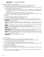
Page 45: ...mportant to make sure that the bobbin tension is properly set first see the tension section for directions on setting the bobbin tension As long as you have your bobbin tension correct you should be able to fix the tension by adjusting only the top tension If you are unable to fix you tension by only adjusting the top tension you may need to re adjust the bobbin tension 36 Maintenance Thread Tensi...

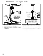
Page 46: ... the machine 2 Raise the Needle to the highest point 3 Loosen the thumb screw that secures the needle a quarter turn Hand tighten Needle Thumb Screw only 37 Maintenance Changing The Needle Old Needle Needle Thumb Screw The eye of the needle faces the bobbin opening New Needle Needle Thumb Screw Be sure to install the needle with the scarf indent toward the throat of your machine ...
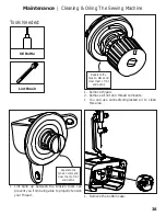
Page 47: ... between the tension discs can prevent you from being able to properly tension your thread 1 Remove the bobbin case Tools Needed Lint Brush Oil Bottle 38 Maintenance Cleaning Oiling The Sewing Machine Separate the tension discs and clear them of lint and debris Separate the tension discs and clear them of lint and debris ...

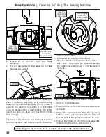
Page 48: ...ne for more than 30 days The head of the machine and the hook assembly are the only areas that require regular lubrication Frequency Once every other bobbin change 1 Remove the bobbin case 2 Ensure all lint and thread remnants have been removed 3 Rotate the hand wheel so that the needle is halfway down about a quarter turn This will put the hook in the optimal position to be oiled 4 Place 1 to 2 d...

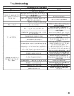
Page 49: ...iming instructions The needle may be damaged Check the needle and replace it if necessary Bobbin may be wound or threaded improperly Check the bobbin to ensure that it is properly wound and that it is properly inserted into the bobbin case Thread may have too much or too little tension Check and readjust your tension Thread Bunches Up Or Is Getting Wrapped Around Hook Holder Hook holder pressing a...

Page 50: ...in thread tensions not balanced Make sure bobbin tension is adjusted correctly Debris on tension discs Clean between and around the tensioner discs Hook holder pressing against hook assembly or doesn t have enough space Readjust the hook holder Bobbin is not correctly wound Check the bobbin to ensure that it is properly wound and that it is properly inserted into the bobbin case Timing needs to be...

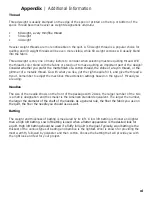
Page 51: ...ou are getting skipped or uneven stitches If you are getting puckered or damaged fabrics If there is a popping or clunking sound made by the sewing machine this may be a sign that the needle is bent After 8 hours of use and at the beginning of each project Shank The part of the needle that is held in the needle bar Shaft The long narrow part of the needle The diameter measurement is based on the s...

Page 52: ...d Cotton thread that has been exposed to a high temperature gas flame very rapidly This process removes fuzz and lint giving the thread a smoother appearance Bonded The thread is treated with a resin to increase its strength Usually used for heavy duty applications such as upholstery Length of Fibers Also know as the staple This is the length of the cotton fibers Extra long staple cotton thread is...

Page 53: ...Remember to adjust the machines thread tension settings based on the type of thread you are using Needles The size of the needle shows on the front of the package with 2 sizes the larger number of the two is a metric designation and the smaller is the American standard equivalent The larger the number the larger the diameter of the shaft of the needle As a general rule the finer the fabric you use...

Page 54: ...The Grace Company 2225 South 3200 West Salt Lake City UT 84119 Phone 1 800 264 0644 Fax 801 908 8888 www graceframe com ...

Reviews: