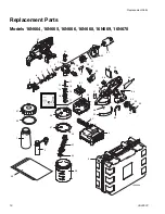

General Service
24
3A2853C
General Service
See manual 3A1884 (available at www.graco.com) for
complete instructions on properly servicing your sprayer.
If you have opened the sprayer clamshell and do not have
access to manual 3A1884, follow the instructions below to
reduce the risk of errors when assembling the sprayer
clamshell.
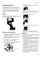
Wiring
Align switch in enclosure, install control board, and route wires
as shown below.
NOTE:
Make sure wires will not be pinched
when enclosure halves are put together.
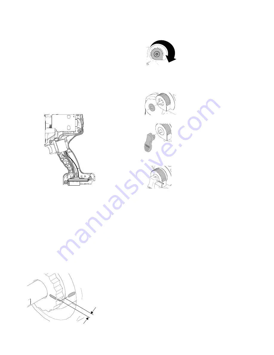
Pressure Control Knob
1.
Use the pressure control knob as a tool to rotate retainer
fully clockwise (there should be no gap between retainer
teeth and metal valve housing).
NOTE:
You may occasionally have to remove, rotate, and
reposition pressure control knob due to stop feature
molded into back of knob.
2.
Rotate retainer back (counter-clockwise) until the first
instance that the line and mark are aligned.
3.
The valve retainer should now protrude approximately 1/8
in. (.30 cm) out from metal valve housing. Your
prime/spray valve is now calibrated.
4.
Position pressure control knob in fully clockwise position
and press firmly onto retainer.
NOTE:
You may have to rotate pressure control knob
slightly counter-clockwise to fully engage pressure control
knob with retainer.
5.
Install washer onto pressure control knob.
6.
Install valve handle onto stem.
7.
Insert pin into valve handle. Use pliers to press pin into
hole.
NOTE:
If pin does not assemble, repeat steps 3 - 6 to
ensure pressure control is fully engaged with retainer.
IMPORTANT!
After assembly is complete, perform the following steps to
verify proper operation. If sprayer fails one of the steps, repeat
Pressure Control Knob
procedure.
•
Verify proper trigger lock operation. Slide trigger lock into
“locked” and “unlocked” position and pull trigger. Trigger
should not move in locked position and sprayer should
run in unlocked position.
•
Visually inspect for gaps between enclosure halves. A
gap larger than 1/32 in. could be caused by a pinched
wire. If disassembly and inspection indicates that no wire
has been pinched, carefully reassemble and repeat
verification steps.
•
Cordless Sprayers:
Verify that battery freely slides onto
sprayer terminals and is locked when fully engaged.
•
Verify belt hook operation (if applicable) by sliding hook
completely out and back inside.
•
Fill material cup with water and verify unit primes and
sprays. Follow setup instructions in sprayer operation
manual for proper priming and spraying procedure.
•
Rotate pressure control knob to make sure it can rotate
fully in both directions.
Cordless models
ti19748a
ti17036a
1/8 in. (.30 cm)
10
ti19716a
ti19717a
ti19713a
ti19712a
Summary of Contents for 16N664
Page 33: ...Notes 3A2853C 33 Notes...


