


10
307–920
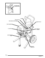
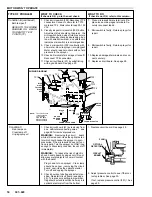
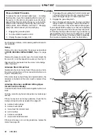
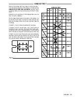
SETUP
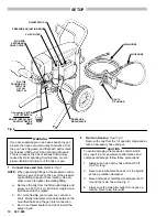
PRESSURE
DRAIN VALVE
MAIN HOSE
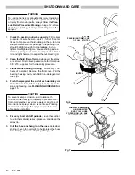
Fig 2
1/4 npsm(m) FILTER
OUTLET NIPPLE
DO NOT INSTALL ANY
SHUTOFF DEVICE
HERE
PLUG FOR
SECONDARY
HOSE OUTLET
ON/OFF SWITCH
PRESSURE ADJUSTING KNOB
FILL THE
PACKING NUT/
WET–CUP
1/3 FULL
WITH TSL
FLUID FILTER
RAC IV
TIP GUARD
WHIP HOSE
If you are supplying your own hoses and spray gun,
be sure the hoses are electrically conductive, that
the gun has a tip guard, and that each part is rated
for at least
3000 psi (210 bar) Working Pressure .
This is to reduce the risk of serious bodily injury
caused by static sparking, fluid injection or over–
pressurization and rupture of the hose or gun.
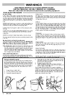
WARNING
1
.
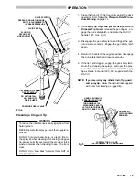
Connect Hose and Gun.
Refer to Fig 2.
NOTE:
When tightening fittings at the pressure control,
hold one wrench firmly on the hex of the pressure
control fitting to keep it from rotating. Use an-
other wrench to tighten the mating fitting.
a. Remove the cap from the filter outlet nipple and
screw on a 50 ft (15.2 m)
(minimum length) main
fluid hose onto the nipple.
b. For more flexible gun movement, connect a
short, smaller diameter, whip hose between the
main fluid hose and the gun inlet connection.
c. Don’t use thread sealant, and don’t install the
spray tip yet!
2. Two Gun Hookup.
See Fig 2.
Remove the cap from the 1/4 npsm(m) nipple
and at-
tach an accessory hose and gun.
CAUTION
To avoid damaging the pressure control, which
may result in poor equipment performance and
component damage, follow these precautions:
1. Always use nylon spray hose at least 50 ft
(15.2 m) long.
2. Never use a wire braid hose as it is too rigid to
act as a pulsation dampener.
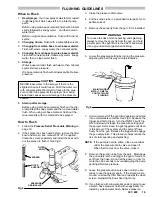
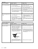
3. Never install any shutoff device between the fil-
ter and the main hose.
See Fig 3.
4. Always use the main filter outlet for one gun op-
eration. Never plug this outlet.
Summary of Contents for 231-081
Page 47: ...47 307 920...


