
307–920
TABLE OF CONTENTS
Introduction
2
. . . . . . . . . . . . . . . . . . . . . . . . . . . . . . . . . . .
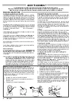
Warnings
4
. . . . . . . . . . . . . . . . . . . . . . . . . . . . . . . . . . . . . .
Avertissement
6
. . . . . . . . . . . . . . . . . . . . . . . . . . . . . . . . .
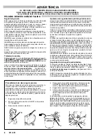
Advertencia
8
. . . . . . . . . . . . . . . . . . . . . . . . . . . . . . . . . . . .
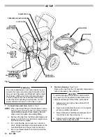
Setup
10
. . . . . . . . . . . . . . . . . . . . . . . . . . . . . . . . . . . . . . .
Operation
13
. . . . . . . . . . . . . . . . . . . . . . . . . . . . . . . . . . . .
Shutdown & Care
14
. . . . . . . . . . . . . . . . . . . . . . . . . . . .
Flushing Guidelines
15
. . . . . . . . . . . . . . . . . . . . . . . . . .
Troubleshooting Guide
Motor Won’t Operate
16
. . . . . . . . . . . . . . . . . . . . . . .
Low Output
19
. . . . . . . . . . . . . . . . . . . . . . . . . . . . . . .
No Output
20
. . . . . . . . . . . . . . . . . . . . . . . . . . . . . . . .
Excessive Pressure Fluctuations
20
. . . . . . . . . . . .
Motor Is Hot and Runs Intermittently
21
. . . . . . . . .
Electrical Short
21
. . . . . . . . . . . . . . . . . . . . . . . . . . . .
Spin Test
22
. . . . . . . . . . . . . . . . . . . . . . . . . . . . . . . . .
Bridge Test
23
. . . . . . . . . . . . . . . . . . . . . . . . . . . . . . .
Repair
General Repair Notes
24
. . . . . . . . . . . . . . . . . . . . . .
Electrical
Motor Brush Replacement
25
. . . . . . . . . . . . . . .
Power Supply Cord Replacement
26
. . . . . . . .
ON/OFF Switch Replacement
26
. . . . . . . . . . .
Bridge Rectifier Replacement
27
. . . . . . . . . . . .
Circuit Breaker Replacement
27
. . . . . . . . . . . .
Circuit Board Replacement
28
. . . . . . . . . . . . . .
Pressure Control Replacement
29
. . . . . . . . . .
Pressure Control Adjustment
30
. . . . . . . . . . . .
Mechanical
Bearing Housing &
Connecting Rod Replacement
32
. . . . . . .
Drive Housing Replacement
33
. . . . . . . . . . . . .
Motor Replacement
34
. . . . . . . . . . . . . . . . . . . .
Displacement Pump Repair
36
. . . . . . . . . . . . .
Parts Lists and Drawings
Displacement Pump
39
. . . . . . . . . . . . . . . . . . . . . . .
Sprayer
40
. . . . . . . . . . . . . . . . . . . . . . . . . . . . . . . . . .
Pressure Control Assembly
42
. . . . . . . . . . . . . . . . .
Wiring Diagram
43
. . . . . . . . . . . . . . . . . . . . . . . . . . . .
Accessories
44
. . . . . . . . . . . . . . . . . . . . . . . . . . . . . . . . .
Technical Data
45
. . . . . . . . . . . . . . . . . . . . . . . . . . . . . . .
Dimensions
45
. . . . . . . . . . . . . . . . . . . . . . . . . . . . . . . . . .
Warranty
Back Cover
. . . . . . . . . . . . . . . . . . . . . . . . . . . .
INTRODUCTION
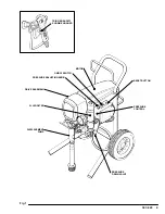
BASIC COMPONENTS
Your new sprayer functions and operates differently than
other airless material sprayers. This section will help you
become familiar with the sprayer before operating it.
Pressure Control
The pressure control includes an ON/OFF switch for the
sprayer, the pressure adjusting control knob, a pressure
sensing device and a current overload circuit breaker with
a manual reset button. The function of the pressure con-
trol is to control the motor speed so that the sprayer main-
tains constant fluid pressure at the pump outlet.
Motor
The DC motor has sealed bearings and replaceable mo-
tor brushes. Its function is to drive the displacement
pump at the rate needed to supply sufficient material vol-
ume at the selected pressure. W orking together , the
pressure control and motor cause the pump to cycle
whenever there is fluid or pressure demand. When the
pump is cycling, the motor sounds like an automobile
starter cranking. When the pump is not cycling, the motor
may hum intermittently until the fluid pressure stabilizes,
then the motor will shut itself off. However, there will still
be power to the sprayer and it will stay pressurized and
ready to use until you manually shut it off and relieve pres-
sure.
Because the motor is DC, it is less sensitive to low voltage
or voltage fluctuations than an AC motor, and a 3-wire, 12
gauge (minimum) extension cord of up to 150 ft. (45 m)
can be used.
Drive Assembly
The sealed drive assembly transfers power from the DC
motor to the displacement pump.
Displacement Pump
The positive displacement, volume–balanced pump pro-
vides equal fluid delivery on both the up and down pump
strokes. The pump has a wet–cup which, when filled with
Graco Throat Seal Liquid, helps prevent damage to the
throat packings and piston rod.
Fluid Filter
The fluid filter strains the material to help avoid clogs in
the hose and spray tip. The filter includes a reusable ele-
ment and has a pressure drain valve for manually reliev-
ing fluid pressure.
Optional Hoses
The grounded, nylon spray hoses have spring guards on
both ends. The 50 ft. (15.2 m) hose has a 1/4 in. ID. The
6 ft. (1.8 m), 3/16 in. ID hose provides more flexible gun
movement. The nylon hose material acts as a pulsation
dampener to absorb pressure fluctuations.
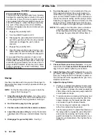
Optional Spray Gun & Tip Guard
The high pressure spray gun has a trigger safety which
prevents accidental triggering when it is engaged.
See
the Detail in Fig 3–1. The gun also has a filter for material
straining. The gun’ s tip guard is a safety feature which
helps reduce the risk of fluid injection injury. NEVER oper-
ate the gun without the tip guard in place.
Summary of Contents for 231-081
Page 47: ...47 307 920...