

20
307–920
WHAT TO CHECK
If check is OK, go to the next check.
TYPE OF PROBLEM
WHAT TO DO
If check is not OK, refer to this column.
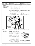
NO OUTPUT
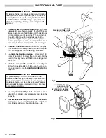
1. Check material supply.
2. Check for clogged intake strainer.
3. Check for loose suction tube or fittings.
4. Check to see if intake valve ball and pis-
ton ball are seating properly. See page
36.
5. Check for leaking around throat packing
nut which may indicate worn or dam-
aged packings. See page 36.
1. Refill and reprime pump.
2. Remove and clean, then reinstall.
3. Tighten; use thread sealant or sealing
tape on threads if necessary.
4. Remove intake valve and clean. Check
balls and seats for nicks; replace if neces-
sary. See page 36.
5. Replace packings. See page 36. Also
check piston valve seat for hardened ma-
terial or nicks and replace if necessary.
Motor runs but pump does not
stroke
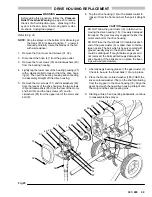
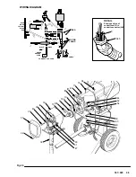
1. Check displacement pump connecting
rod pin. See page 32.
2. Check connecting rod assembly for
damage. See page 32.
3. Be sure crank in drive housing rotates;
plug in sprayer and turn on momentarily
to check. Turn off and unplug sprayer .
See page 33.
1. Replace pin if missing. Be sure retainer
spring is fully in groove all around con-
necting rod. See page 32.
2. Replace connecting rod assembly . See
page 32.
3. Check drive housing assembly for dam-
age and replace if necessary. See page
33.
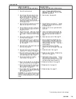
Motor runs and pump strokes
WHAT TO CHECK
If check is OK, go to the next check.
TYPE OF PROBLEM
WHAT TO DO
If check is not OK, refer to this column.
Spray pattern variations.
1. Be sure both G1 and G2 leads from
bridge (308) to circuit board (118) are
firmly connected. See page 28.
2. Check pressure control adjustment. Re-
fer to procedure on page 30.
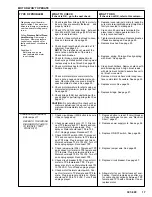
3. Check bourdon tube flag and detector
position. Turn pressure setting to maxi-
mum; flag should not drag or bind in opti-
cal detector slot of circuit board.
4. Check circuit board (118) by substituting
with a good board. See page 28.
5. Check LOW OUTPUT section on page
19.
1. Reconnect securely. See page 28.
2. Adjust pressure control. See page 30.
3. Carefully bend flag into alignment with
detector slot to see if that corrects prob-
lem. If not, replace pressure control as-
sembly (301)
@
. Adjust pressure control
after reassembly.
4. Replace circuit board. See page 28.
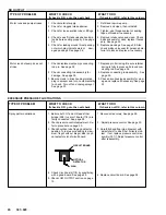
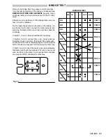
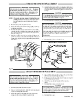
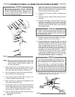
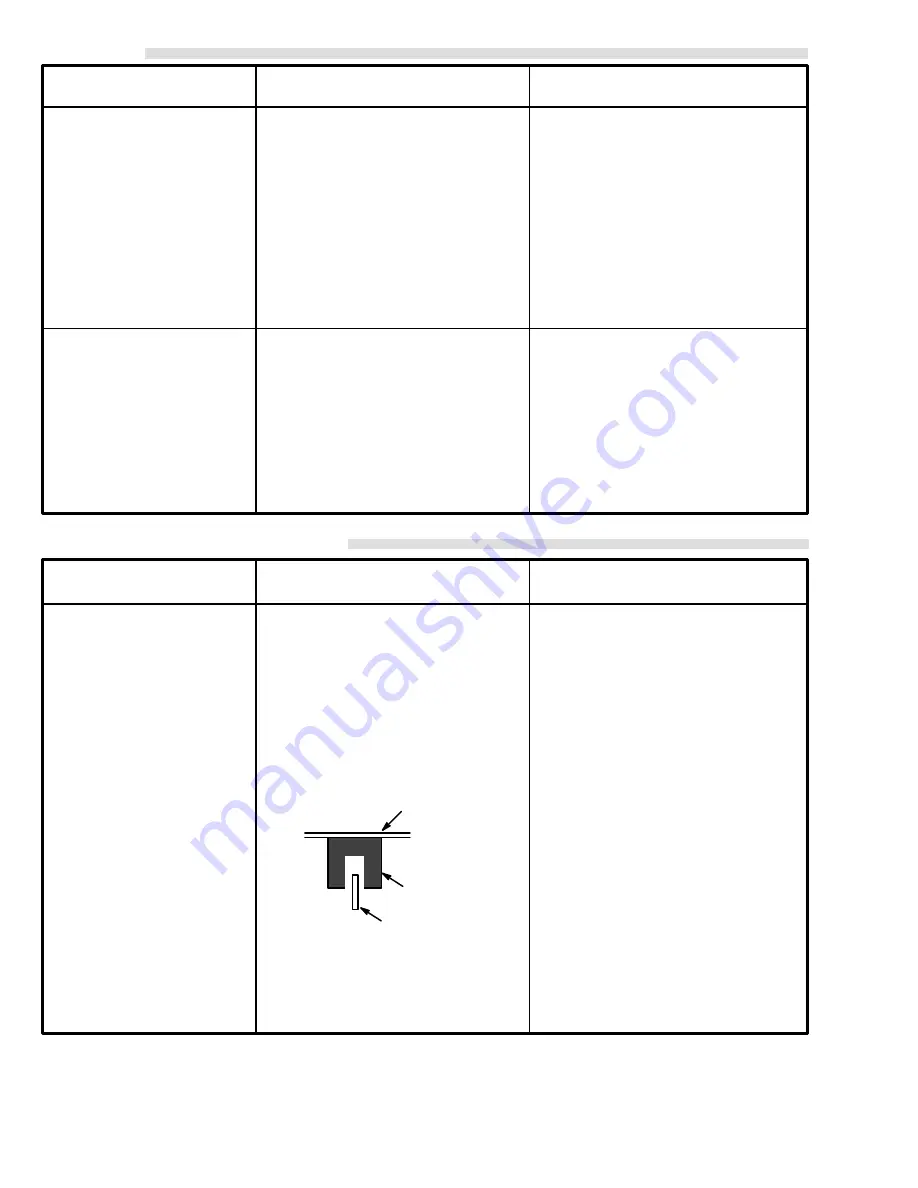
EXCESSIVE PRESSURE FLUCTUATIONS
CIRCUIT BOARD
OPTICAL
DETECTOR
FLAG
Summary of Contents for 231-081
Page 47: ...47 307 920...


