

28
307–920
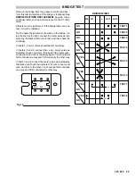
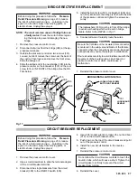
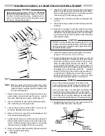
CIRCUIT BOARD REPLACEMENT
Before doing this procedure, follow the
Pressure
Relief Procedure Warning
on page 23 to reduce
the risk of a fluid injection injury , splashing in the
eyes or on the skin, injury from moving parts, or
electric shock.
Unplug the sprayer!
WARNING
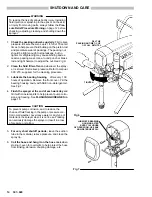
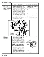
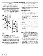
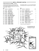
Refer to Fig 18 and 19.
1. Remove the pressure control cover.
2. Turn the pressure control knob to the minimum set-
ting to release spring tension on the board. Check to
be sure only three or four threads of the pressure
control knob shaft are exposed below the pressure
adjustment nut (S). Loosen the nut, if necessary. Re-
fer to Fig 18.
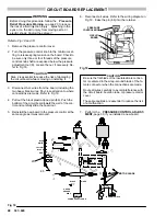
CAUTION
Step 2 is essential to reduce the risk of damaging
the circuit board while removing or installing it.
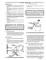
3. Disconnect ALL wires from the board, including the
two heavy black wires. Pay close attention to where
connections are made. Refer to Fig 19.
4. Pull out the black plastic–tipped pin (86). Push the
bottom of the circuit board toward the wall of the con-
trol and carefully slide the board out.
5. Reinstall the new board in the pressure control at the
same angle as it was removed.
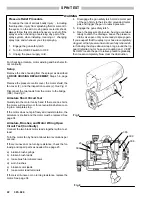
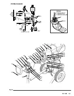
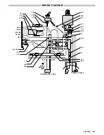
6. Reconnect all wires. Refer to the wiring diagram in
Fig 19. Ease the pin (86) into the retainer.
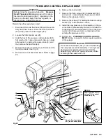
PRESSURE
CONTROL KNOB
CIRCUIT
BOARD
86
S
Fig 18
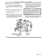
CAUTION
Be sure the flat blade of the insulated male connec-
tor is centered in the wrap–around blade of the fe-
male connector when the connections are made.
Route all wires carefully to avoid interference with
the circuit board, bourdon tube, or pressure control
cover.
These precautions are essential to reduce the risk
of a malfunction.
7. Perform the
PRESSURE CONTROL ADJUST-
MENT,
page 30, if you installed a new board.
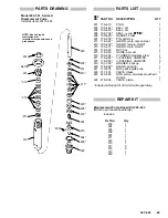
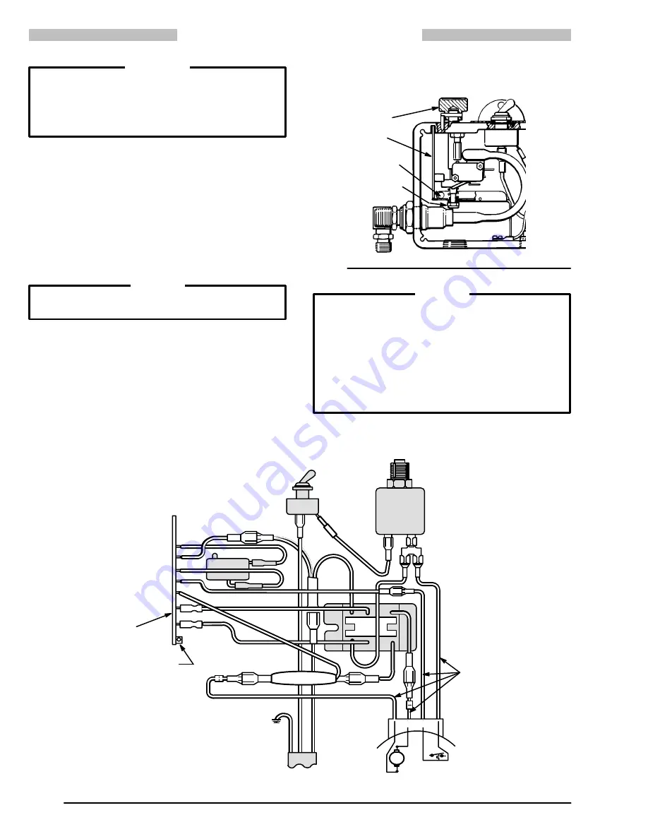
Fig 19
AC1
AC2
G1
G2
_
+
WHITE
BLUE
YELLOW
RED
GREEN
BLACK
WHITE
THERMAL SWITCH
GROUND
WIRE
BLACK
POWER SUPPLY CORD
MOTOR
86
MOTOR LEADS
23
Summary of Contents for 231-081
Page 47: ...47 307 920...


