

29
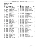
307–920
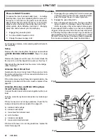
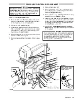
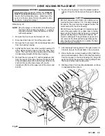
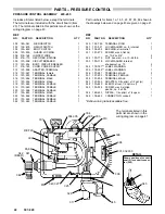
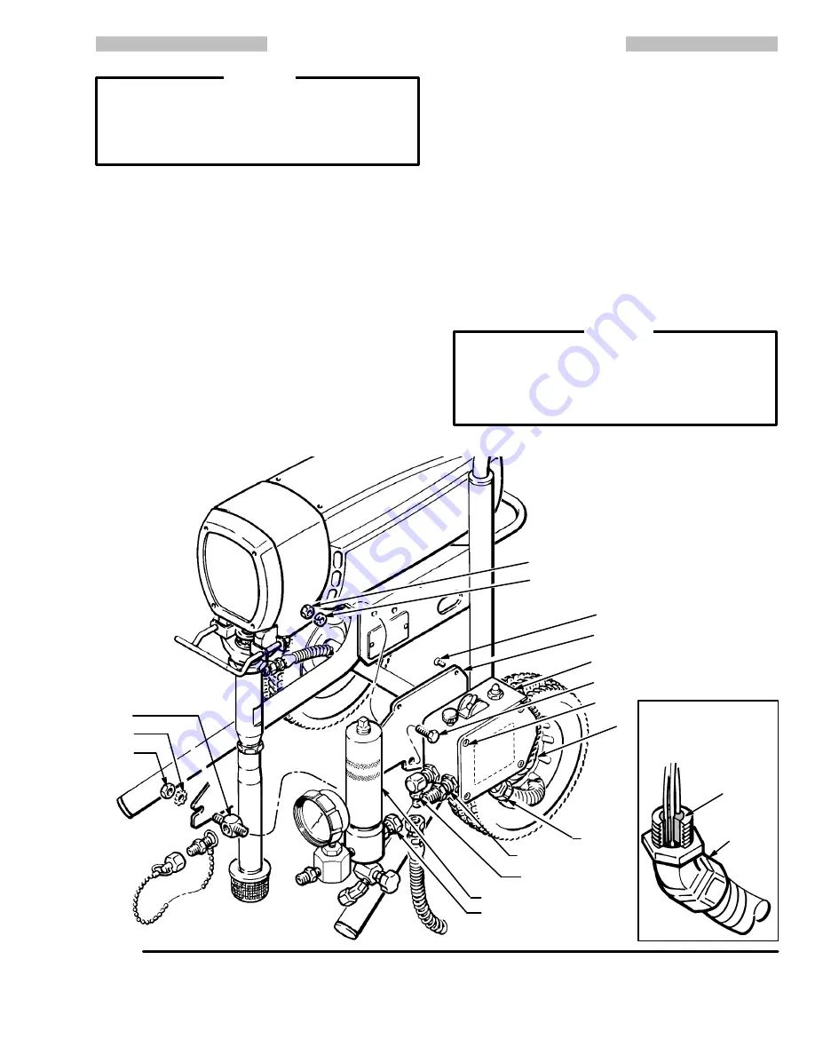
PRESSURE CONTROL REPLACEMENT
Before doing this procedure, follow the
Pressure
Relief Procedure Warning
on page 23 to reduce
the risk of a fluid injection injury , splashing in the
eyes or on the skin, injury from moving parts, or
electric shock.
Unplug the sprayer!
WARNING
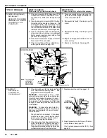
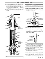
Refer to Fig 20 except where noted.
1. Disconnect the main fluid hose (90) and the secon-
dary fluid hose, if used. Disconnect the fluid hose
(47) at the pressure control nipple (344).
2. Loosen the filter bracket nut (28).
3. Hold the hex of the pressure control adapter (341)
firmly with a 3/4” open end wrench. Use an adjust-
able wrench to unscrew the swivel union (8), and
then remove the fluid filter (48).
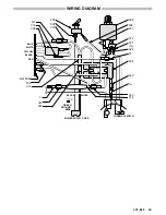
4. Remove the pressure control cover. Disconnect the
four motor leads.
See Fig 19.
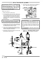
5. Remove the circuit board and retain. Refer to page
28.
6. Remove the conduit (22).
7. Remove the three screws (44), lockwashers (40),
and nuts (41) located below the pressure control.
Remove the pressure control.
8. Remove the screws (15) holding the back mounting
bracket (16) to the pressure control.
9. Install the new pressure control assembly in the re-
verse order of disassembly. Be sure to reinstall the
conduit seal (5) around the wires in the conduit con-
nector (345) to prevent motor contamination from
entering the pressure control.
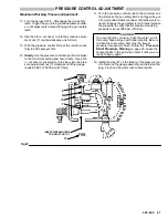
10. Perform the
PRESSURE CONTROL ADJUST-
MENT
starting on page 30, before regular operation
of the sprayer.
CAUTION
Do not allow the adapter (341) to turn while installing
the new pressure control assembly . Turning it can
damage the sensitive bourdon tube. Hold the
adapter firmly with a 3/4” open end wrench while
screwing In the swivel union (8).
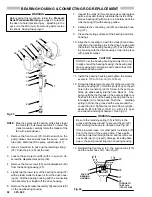
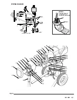
Fig 20
8
36,84
13
28
344
341
44
43
16
15
41
40
34
48
22
345,5
Do not allow the adapter
(341) to turn at any time.
DETAIL
Shows position of con-
duit seal (5) in conduit
connector (345)
5
345
Summary of Contents for 231-081
Page 47: ...47 307 920...


